
Aerosol deliver apparatus IV

Inactive Publication Date: 2005-10-06
DHUPER SUNIL +1
View PDF4 Cites 69 Cited by
  • Summary
  • Abstract
  • Description
  • Claims
  • Application Information

AI Technical Summary

Benefits of technology

[0035] The present invention provides an aerosol medication delivery apparatus, which incorporates the aforementioned advantages. The inventive device includes a fixed volume or a collapsible / expandable MDI holding chamber, a fixed volume or a collapsible / expandable nebulizer chamber, a system of connecting the two chambers with 2 or more hollow collapsible / expandable or fixed volume cylindrical connecting tubes. The MDI holding chamber maybe a fixed volume chamber or a collapsible / expandable chamber or a combination of the two i.e., partly fixed and partly collapsible / expandable chamber. The collapsible feature of the device makes it compact when solely in use for delivery of single gas or different gas mixtures while the expandable feature can be utilized when delivering aerosol medication with an MDI and / or a nebulizer.
[0036] The collapsible / expandable MDI chamber has a hollow cylindrical rigid inlet port at one end and a similar outlet port at the other end. When fully collapsed the outlet and the inlet port may be fused to each other to form a continuous hollow rigid cylindrical tube. When the holding chamber is fully expanded the outlet and inlet tubes stay disconnected. The holding chamber may be kept patent by internal support with a coiled metal or plastic wire. The rings of the coiled wire come together when the chamber is collapsed and stay separated when it is expanded. Alternatively, the MDI chamber may be constructed with a collapsible / expandable corrugated plastic tubing, which does not require any coiled metal or plastic wire support for maintaining patency of the chamber. The volume of the chamber may vary form 0.10 liters to 2.0 liters to accommodate both pediatric and adult patients. When partially or fully expanded, the chamber may also serve as a reservoir to prevent aerosol generated during exhalation from being wasted.
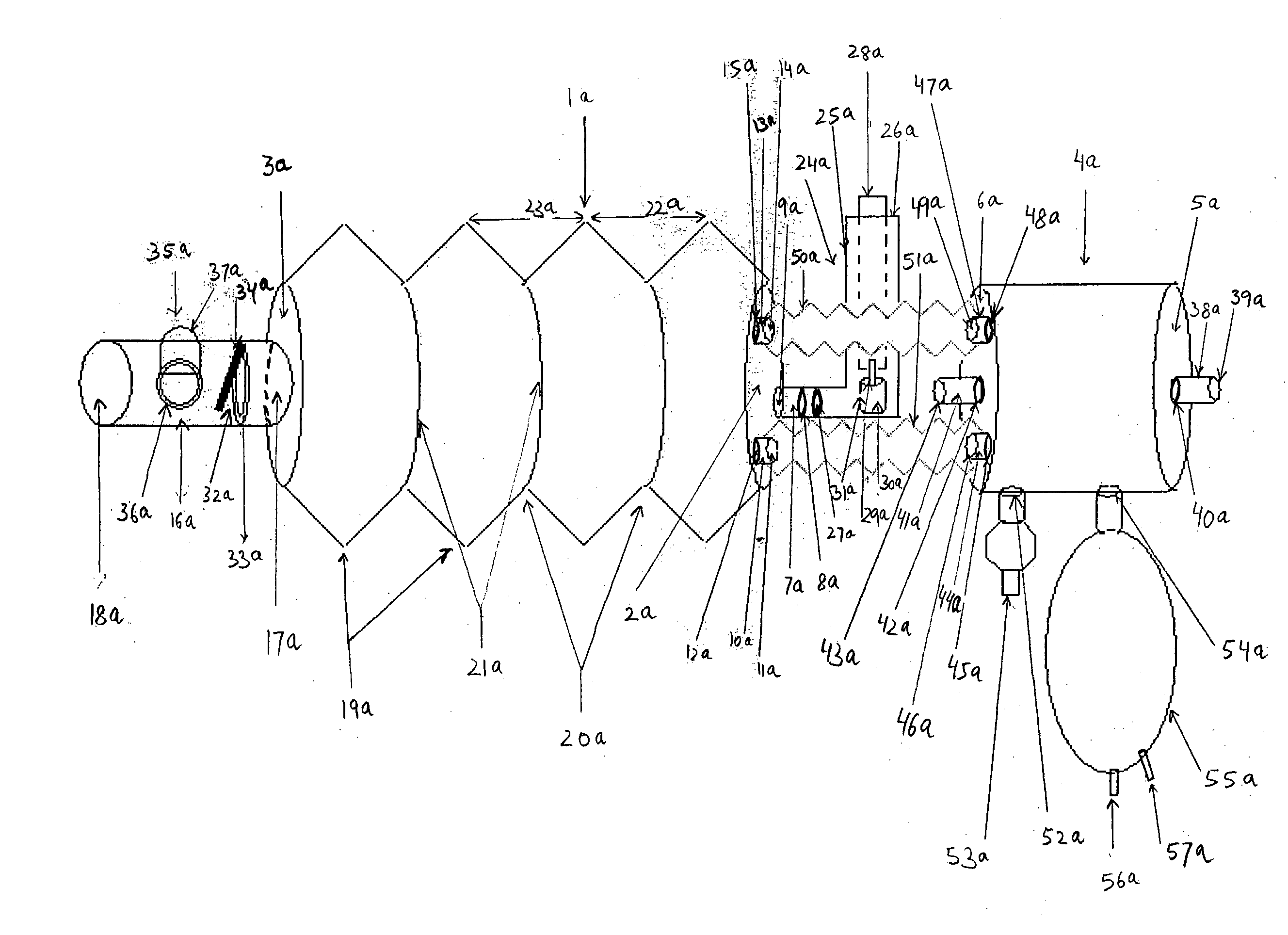
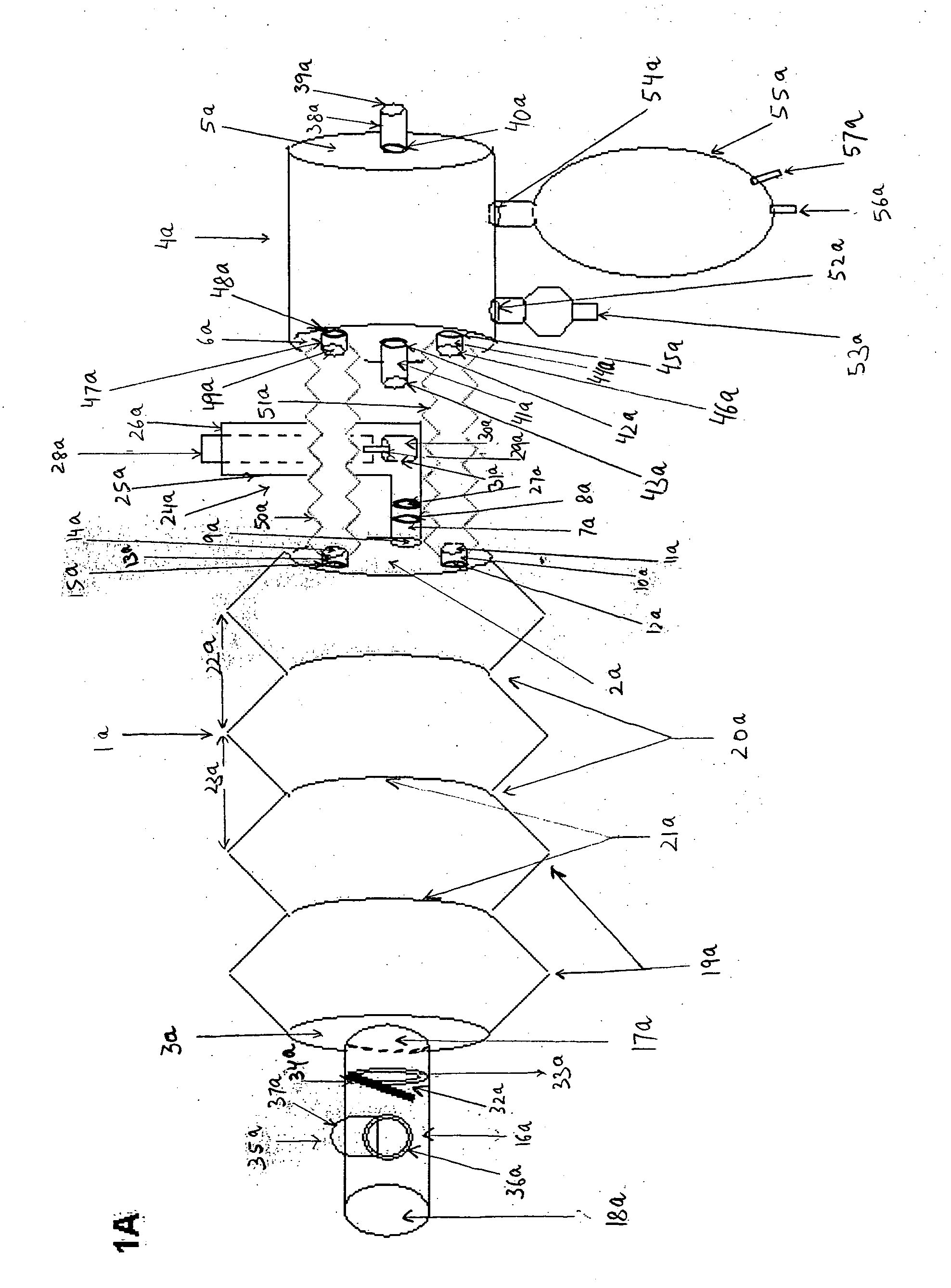
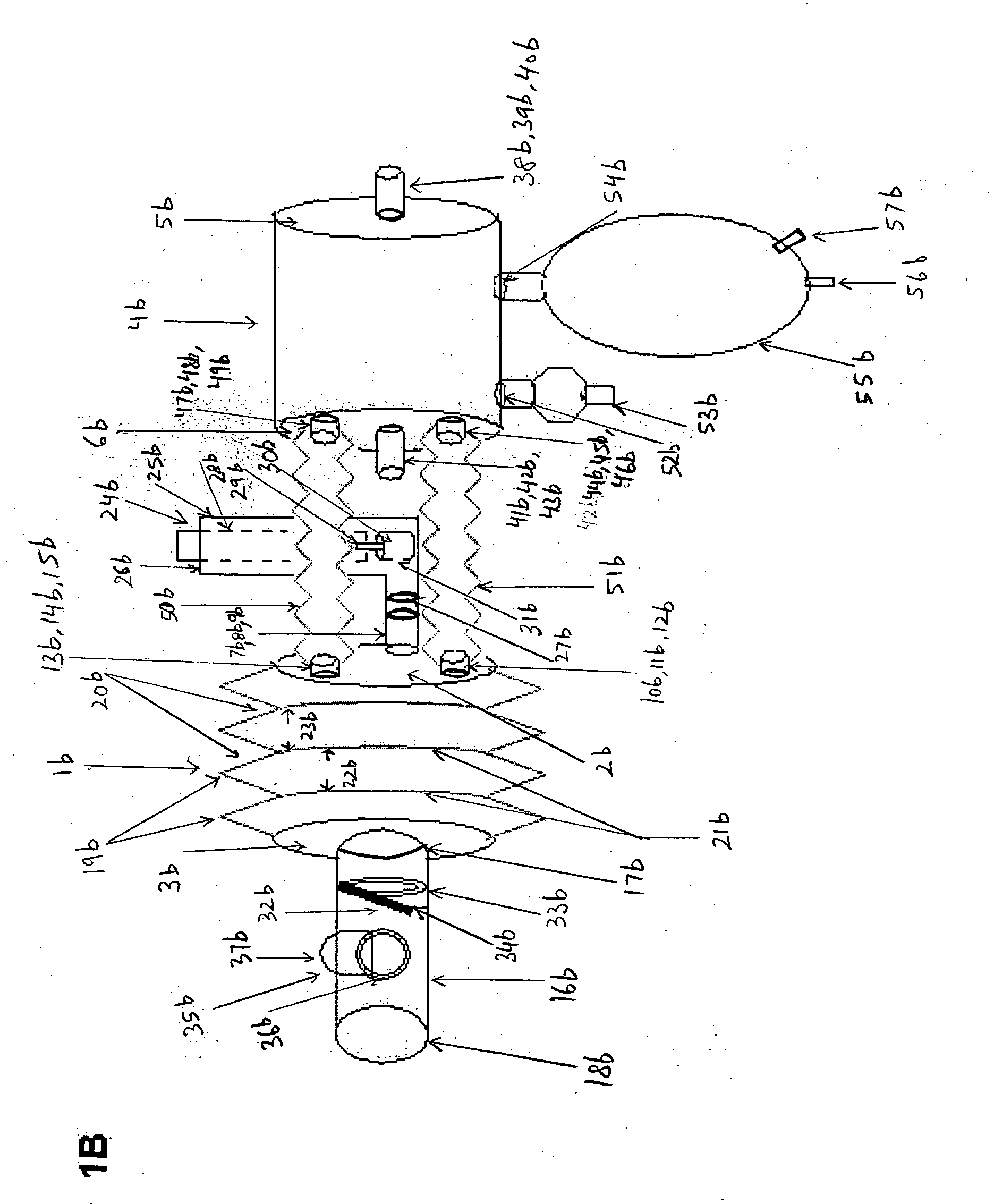
[0037] The central rigid inlet port is connected to a universal boot adapter panel with an opening to accommodate the boot of any commercially available MDI such that medication can be delivered to the MDI chamber on actuation of the MDI canister. For aerosol delivery with nebuliser, the universal boot adapter is disconnected from the inlet port, which now fuses with the outlet port of the nebulizer chamber. The inlet of the MDI chamber is connected to the outlet to the nebulizer chamber with two additional peripheral hollow cylindrical connecting tubes; the two tubes have two outlet ports at 3 and 9 o'clock positions in the nebulizer chamber and two inlet ports in similar locations in the MDI chamber. The distance between the connecting tubes and the length of the connecting tubes allows for any commercially available MDI boot to be accommodated easily between the MDI and the nebulizer chambers. At the inlet end of the MDI chamber, the peripheral hollow cylindrical connecting tubes split into multiple micrometric openings that are distributed at intervals along the entire circumference of the MDI chamber's inlet. This allows the flow of gas(es) from the two openings in the nebulizer chambers outlet to the multiple openings distributed all along the circumference of the MDI chamber's inlet. The pattern of flow of the gas(es) through multiple openings that are distributed along the circumference of the MDI chamber's inlet is such that it does not interfere with the plume of the MDI when it is actuated. Also this arrangement allows different desired density gas(es) with a desired fraction of inspired oxygen to flow into the MDI chamber to enhance aerosol delivery from MDI and to deliver oxygen to a patient if necessary. The flow pattern of the gas(es) in addition minimizes the impaction losses of aerosol generated by an MDI.
[0038] The outlet rigid tube of the MDI chamber has an inhalation flap valve and a flap seat. The flap valve moves away from the flap valve seat on inhalation to allow the flow of medication from the MDI chamber to the patient. On exhalation the flap valve presses against the flap valve seat which prevents carbon dioxide exhaled during exhalation from entering into the MDI chamber. The outlet tube has an exhalation flap valve assembly with an exhalation flap valve and a valve seat on the superior or inferior surface. The flap valve moves away from the flap valve seat on exhalation to allow the exhaled gases to exit the outlet tube and presses against the valve seat on inhalation to prevent any entrainment of any room air gases on inhalation. The provision of a filter at this opening may be optional depending on the conditions under which aerosol is being delivered. The filter can trap all exhaled aerosol particles while allowing the gases to exit from this port. A flap valve may again be provided at the end of the filter to prevent entrainment of room air gas during inhalation and to allow exit of all exhaled gas(es).
[0039] The nebulizer chamber has an inlet port with a central cylindrical hollow rigid tube for entry of one or more gases into the nebulizer chamber; an outlet port, a port for a nebulizer, and a port for a reservoir (a bag reservoir or a collapsible / expandable corrugated plastic tubing reservoir), the reservoir bag has one or more inlet ports for inflow of desired gases. There are two additional openings at 3 and 9 o'clock positions for connection of peripheral tubes that connect the MDI chamber and the nebulizer chamber. The outlet of the nebulizer chamber has a rigid hollow cylindrical tube similar to that seen in the MDI chamber's inlet. The port of the nebulizer chamber remains plugged with a cap when MDI is in use. The cap is unplugged and the outlet port of the nebulizer fuses with the inlet port of the MDI chamber when nebulizer is to be used. When aerosol delivery is desired with a nebulizer, the nebulizer is connected to the nebulizer port, the nebulized medication flows through the peripheral connecting tubes between the MDI chamber and the nebulizer chamber through multiple openings distributed along the circumference of the MDI chamber's inlet. The universal boot adapter assembly may be disconnected from the central rigid tube of MDI the chamber, which could now be plugged with a cap. Alternatively, the central inlet tube of the MDI chamber and the central outlet tube of the nebulizer chamber can both uncapped and the two tubes fused to each other by moving the MDI chamber closer to the nebulizer chamber by collapsing the peripheral connecting tubes. The aerosol generated by the nebulizer can now flow from the nebulizer chamber to the MDI chamber via the central connection between the MDI chamber and the nebulizer chamber, as well as via the peripheral connections between the two chambers via the peripheral connecting tubes at 3 and 9 o'clock positions. The connecting tubes between the MDI and nebulizer chambers are made collapsible / expandable in a manner identical to the principles of the expandable / collapsible MDI chamber itself. This will allow the MDI and the nebulizer chambers to be moved closer to each other to be fused during nebulizer operation or to be disconnected and moved apart to accommodate MDI in the space between the MDI and the nebulizer chambers during MDI operation.

Problems solved by technology

Patients can self-administer the MDI medication using the boot alone but the majority of patients have difficulty in synchronizing the actuation of the MDI canister and inhalation of the medication.
These devices are expensive and may be alright for chronic conditions that require frequent use of MDI inhalers provided the cost and labor involved in frequent delivery of medication is acceptable to the patient.
However, under acute symptoms, such devices may fail to serve the purpose and lead to an inadequate delivery of medication.
Nebulizers are fraught with numerous problems as well.
The medication dose used is about 10 times of that used with an MDI and hence the increased cost without any added proven clinical benefit.
Secondly, the majority of the nebulized medication is wasted during exhalation.
Thirdly, the time taken to deliver the medication is several times that of an MDI and the labor cost of respiratory therapist may outweigh the benefits of nebulizers compared with MDIs.
However, these devices are expensive and still have all the other problems associated with nebulizer use alone.
Problems with prior art devices such as described are a significant waste of medication, a non-uniform concentration of delivered medication, expensive, and difficult to use.
All the afore mentioned devices can be used with either an MDI or a nebulizer but not both, and hence, face the difficultly associated with either system alone.
However, the device is plagued with problems typical of such devices.
Just like other prior art devices, this device as well fails to incorporate some of the key the features necessary for enhanced aerosol delivery.
A list of problems associated with this device and other similar devices are outlined below: (1) The entrained airflow in this device interferes with the MDI plume as well as the plume generated by a nebulizer resulting in increased impaction losses of aerosol generated by either an MDI or nebulizer.
(2) The device does not have the ability to deliver a desired precise fraction of inspired oxygen to a hypoxic patient and simultaneously deliver aerosol medication with either a metered dose inhaler or a nebulizer.
(3) The device cannot deliver a gas with a desired density to improve aerosol delivery and a desired fraction of inspired oxygen to a hypoxemic patient (4) The device does not have the ability to deliver different density gases with a desired fraction of inspired oxygen simultaneously while retaining the ability to deliver aerosol medication at the same time with either an MDI or a nebulizer (5) the device does not have the ability to deliver a mixture of multiple gases to a patient and simultaneously maintain a desired fraction of inspired oxygen (6) the device does not serve as a facemask for delivering varying concentrations of inspired oxygen from room air to 100% but serves solely as an aerosol delivery device (7) the device does not have a reservoir chamber-either as a bag or as a large volume tubing t store nebulized medication that is otherwise wasted during exhalation.
The holding chamber of this device varies from 90 cc to 140 cc and is not enough to serve as a reservoir for the volume of nebulized medication generated during exhalation and hence in a normal sized adult most of the medication generated during exhalation is wasted (8) there is no mechanism in the device to prevent entrainment of room air which forms the bulk of volume during inhalation.
Rebreathing of carbon dioxide from the holding chamber on subsequent inhalation can be extremely detrimental to a patient and extremely dangerous under certain clinical conditions (10) the device does not have the capability of delivering medication with an MDI and a nebulizer simultaneously (11) the device has a fixed volume-holding chamber, which makes the device extremely large and cumbersome to deliver medication.

Method used


Image

  • Aerosol deliver apparatus IV
  • Aerosol deliver apparatus IV
  • Aerosol deliver apparatus IV

Examples


Embodiment Construction

[0074] The present invention will now be described in detail by reference to the drawing figures, where as like parts as indicated by like reference numerals.

[0075]FIG. 1A is a plan view of the longitudinal length of aerosol delivery apparatus IV according to one embodiment of the present invention, incorporating the features described in the summary of the invention. FIG. 1A is a plan view of the invention that may be used with a metered dose inhaler (MDI) or a nebulizer. The illustration here describes the use of this device preferentially with an MDI. The device has two hollow chambers, a metered dose inhaler chamber 1a, and a nebulizer chamber 4a. The MDI chamber 1a has an inlet end 2a and an outlet end 3a. The nebulizer chamber 4a similarly has an inlet end 5a and an outlet end 6a. The inlet end 2a has three hollow cylindrical inlet tubes, a central tube 7a and two peripheral tubes 10a and 13a located at three o'clock to nine o'clock positions, respectively. The central hollow...


PUM


Abstract

A multipurpose aerosol medication delivery apparatus that includes a collapsible / expandable, or a fixed volume, or a combination of partially fixed volume and partially collapsible / expandable holding chamber for use with a metered dosed inhaler (MDI) and / or any standard small volume nebulizer. The holding chamber is designed to deliver-aerosol medication particles generated by an MDI; aerosol medication particles generated by a nebulizer; a single gas or a mixture of gases; a single gas or a mixture of gases that can yield a gas density that will enhance aerosol delivery of medication with both MDI and nebulizer; a single gas or a mixture of gases that will yield and deliver an oxygen concentration to a patient ranging from room air concentration to 100%. The device includes a reservoir that stores nebulized aerosol generated during exhalation to be inhaled during the next breath. The device also included a one way valve to prevent carbon dioxide generated during exhalation from rebreathing by not allowing the exhaled air from entering the holding chamber. The device includes an exit port with a second one way valve that allows the exhaled air to exit the device but closes during inhalation to prevent any entrainment of room air gas. The exit port may instead have a filter with one-way valve to trap the exhaled aerosol particles while allowing the exhaled gases to escape. The filter valve will similarly close during inhalation to prevent entrainment of room air gas. The holding chamber will allow a uniform mixture of aerosol medication and gases to flow together during inhalation to the patient via a mouthpiece or a facemask. The holding chamber is connected to a nebulizer chamber with a single or multiple connecting tubes that allow gas mixtures with varying density, viscosity, humidity and concentration of oxygen to flow into the holding chamber from the nebulizer chamber. The pattern of flow of the gas(es) does not disturb the flow of the nebulized medication from the nebulizer chamber to the holding chamber or interfere with the plume generated by an MDI. The device also serves as a facemask for delivering precise concentrations of oxygen or as a 100% non-rebreather mask. The device also serves to deliver precise concentrations of different density gases i.e. nitrogen, helium, oxygen, etc. This will allow varying fractions of inspired oxygen to deliver aerosol medication via MDI or a nebulizer. Thus, the device has the ability to deliver aerosol medication with an MDI or a nebulizer while retaining the ability to simultaneously deliver different density gas mixtures and varying fraction of inspired oxygen without interrupting one for the other.

Description

CROSS-REFERENCE TO RELATED APPLICATIONS [0001]3967619July, 1976Story et al.4484577November, 1984Sackner et al.128 / 2004534343August, 1985Nowacki et al.128 / 2034790305December, 1988Zoltain et al128 / 2034823784April, 1989Bordoni et al.4926852May, 1990Zoltain et al.128 / 2035020530June, 1991Miller et al.5027806July, 1991Zoltain et al.128 / 2035752502May 1998King et al.128 / 2004819629April, 1989Jonson128 / 200D272559February, 1984GuthD24 / 110D295321April, 1988HollworthD24 / 110D342993January, 1994FathiD24 / 110D373630September, 1996Berg et al.D24 / 1105139016August, 1992Waser128 / 2005178138January, 1993Walstrom et al.128 / 2005063921November, 1991Howe128 / 200D442685May, 2001Sladek5738087April, 1998Key128 / 2005497765March, 1996Proud, et al128 / 2005431154July, 1995Siegel et al.128 / 2005078131January, 1970Greenfield128 / 2005320094June, 1994Lombe et al.128 / 2005617844April, 1997King128 / 2003187748June, 1995Mitchell et al.128 / 2005848587December, 1998King128 / 200US Pat. App.September, 2002Johnson#20020121275BACKGROUND O...

Claims


Application Information

Patent Timeline
Patent Type & Authority Applications(United States)
IPC IPC(8): A61M11/00A61M15/00
CPCA61M15/0086A61M15/0088A61M15/009
Inventor DHUPER, SUNILDHUPER, SARITA
Owner DHUPER SUNIL
Learn More