
Apparatus for manufacturing thermosetting powder coating compositions with dynamic control including low pressure injection system

a technology of dynamic control and injection system, which is applied in the field of manufacturing powder coating compositions, can solve the problems of significant waste of product, increased production cost, and reduced product quality, and achieve the effect of reducing product loss

Inactive Publication Date: 2005-09-29
PPG IND OHIO INC
View PDF31 Cites 34 Cited by
  • Summary
  • Abstract
  • Description
  • Claims
  • Application Information

AI Technical Summary

Benefits of technology

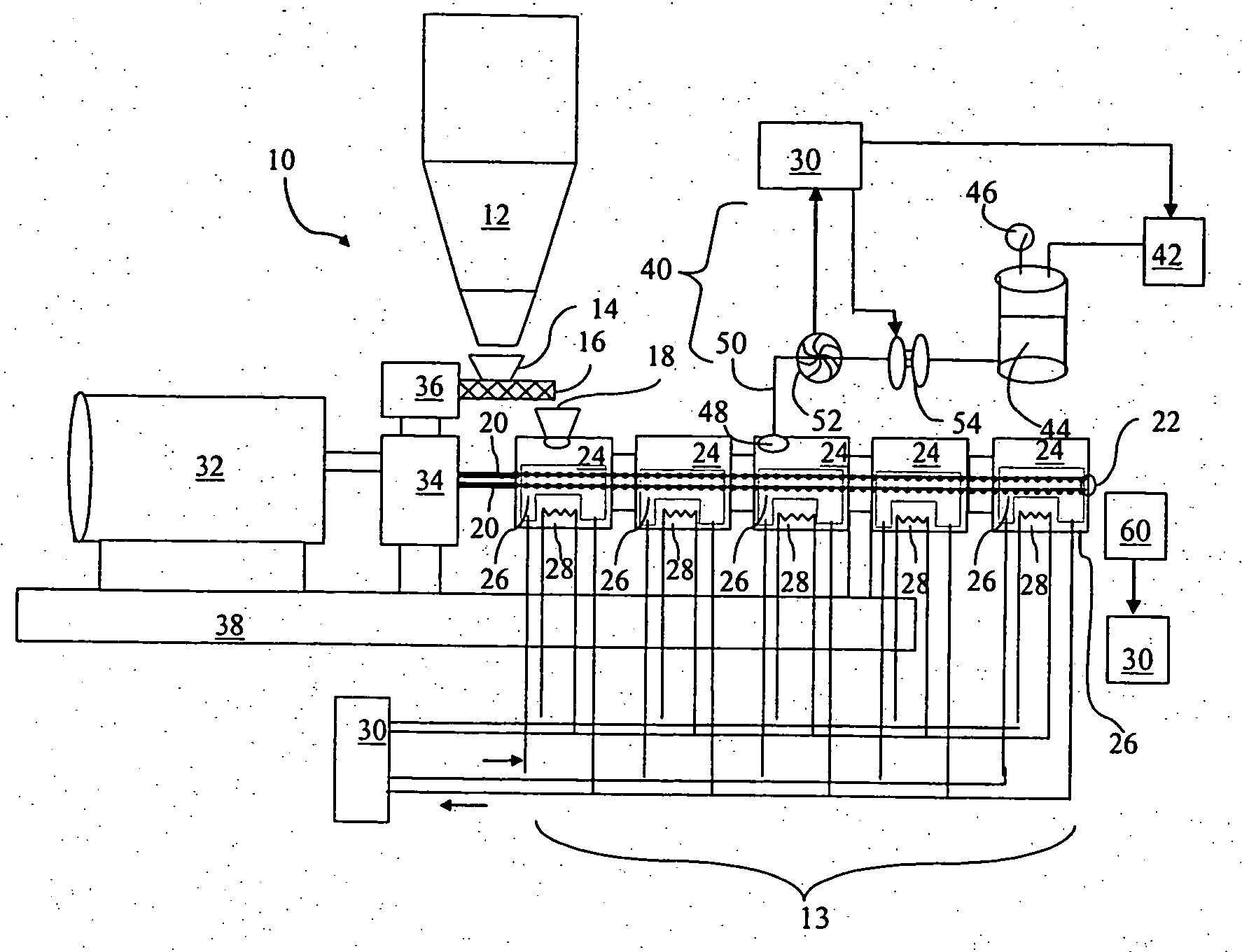
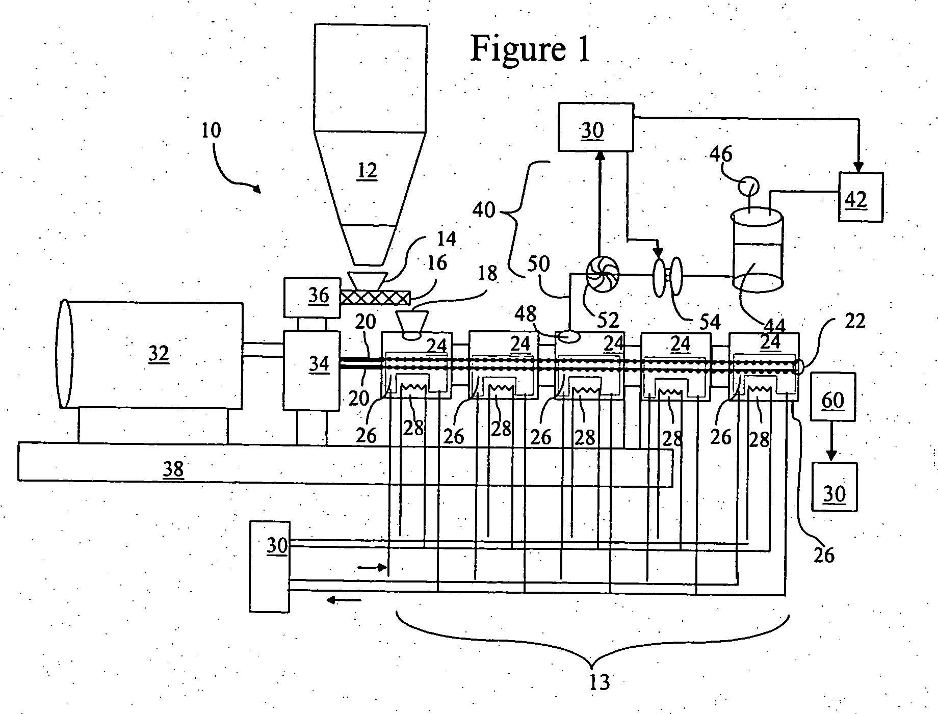
[0005] The present invention provides an extruder system for manufacturing thermosetting powder coating compositions that maintains adequate dispersion of ingredients within the extrudate and includes an additive injection system with dynamic control; the present extruder system also allows rapid change out between runs of different colors and / or formulations. The present process for manufacturing powder coating compositions decreases product loss due to color control by using an additive pigment injector system.

Problems solved by technology

Specifically, powder coatings do not contain volatile organic solvents that evaporate during application or curing; omitting solvent results in considerable environmental and costs savings.
The conventional powder-forming process can result in significant wasted product if the formulation is not precise.
Additional waste can be generated if pigment and / or other hard to incorporate components of the powder do not adequately blend to form a homogeneous material.
Further, the color changes and / or formulation changes from one batch to the next require extensive and time-consuming cleaning of the pre-mix hopper and the extruder body.

Method used


Image

  • Apparatus for manufacturing thermosetting powder coating compositions with dynamic control including low pressure injection system
  • Apparatus for manufacturing thermosetting powder coating compositions with dynamic control including low pressure injection system

Examples


Embodiment Construction

[0007] The present invention is directed to an extruder comprising one or more rotating screws, and a plurality of adjacent segments surrounding the rotating screw(s). Optionally, a pre-mix hopper can be located upstream of the screws. Each segment includes a cooling system for cooling material in the segment, and a heating system for heating material in the segment, wherein the cooling systems and the heating systems of each segment can be selectively, independently operated. One segment has a main inlet for receiving material such as from the pre-mix hopper, and a final segment has an outlet for discharging material from the extruder. The extruder of the present invention further comprises an additive injector adapted to inject additives into one or more segments at one or more additive injection positions between the main inlet and the outlet.

[0008] The additive injector includes a low pressure vessel, and a flow regulator between the pressure vessel and the intermediate injecti...


PUM

PropertyMeasurementUnit
Pressureaaaaaaaaaa

Abstract

A thermosetting powder coating composition extruder system including an extruder body and an injection system is disclosed. The extruder body includes segments surrounding one or more rotating screws. A first segment's main inlet receives material, such as from a pre-mix hopper, and a final segment's outlet discharges extrudate. A low pressure injector injects additives, particularly those that are hard to incorporate, into one or more segments at one or more injection positions at the main inlet or between the main inlet and the outlet. The injector includes a source of pressurization coupled to a pressure vessel, a pressure regulator maintaining the pressure at or below a given level, a flow regulator, and an injection port. A sensor adjacent the outlet monitors the physical characteristics of the extrudate and is coupled to a controller of the low pressure injector for dynamic control thereof.

Description

FIELD OF THE INVENTION [0001] The present invention relates to the field of manufacturing powder coating compositions, and in particular to an extrusion system for forming thermosetting powder coating compositions with dynamic control having a low pressure injection system. BACKGROUND OF THE INVENTION [0002] Powder coating compositions are well known in the industry and have been prepared by various methods. The use of powder coatings has grown dramatically primarily due to their environmental advantages over liquid coatings, e.g. solvent based coatings. Specifically, powder coatings do not contain volatile organic solvents that evaporate during application or curing; omitting solvent results in considerable environmental and costs savings. For example, conditioned air from powder paint booths may be recycled rather than exhausted because it does not contain solvent vapor. Further, powder coating overspray is easily captured and recycled without the use of a water-wash system, elimi...

Claims


Application Information

Patent Timeline
IPC IPC(8): B29C35/02B29C35/16B29C48/04B29C48/08B29C48/17B29C48/29B29C48/92
CPCB29C47/0011B29C47/043B29C47/1063B29C47/82B29C47/8845B29C47/885B29C47/92B29C2035/0211B29C2035/1616B29C2947/92104B29C2947/92238B29C2947/92247B29C2947/92409B29C2947/92514B29C2947/926B29C2947/92704B29C2947/92742B29C2947/92828B29C2947/92895B29K2105/0005B29K2105/0032B29K2105/251B29K2995/002B29C47/0021B29C48/83B29C48/92B29C2948/92409B29C2948/92704B29C48/29B29C48/04B29C48/08B29C48/17B29C48/832B29C48/834B29C48/914B29C48/9145B29C2948/92104B29C2948/92238B29C2948/92247B29C2948/92514B29C2948/926B29C2948/92742B29C2948/92828B29C2948/92895B29B7/826B29B7/823B29B7/38B29B7/603B29B7/72
Inventor FERENCZ, JOSEPH M.AMMONS, CHARLES A.DENK, GREGORY J.
Owner PPG IND OHIO INC
Learn More