
DC regulated power supply comprising

a technology of dc regulated power supply and power supply circuit, which is applied in the direction of pulse technique, process and machine control, instruments, etc., can solve the problems of damage to load, input current also becomes dull, and the operation of the protection circuit influences other problems, so as to achieve the effect of suppressing the fluctuation of output voltag

Inactive Publication Date: 2005-09-29
SHARP KK
View PDF8 Cites 0 Cited by
  • Summary
  • Abstract
  • Description
  • Claims
  • Application Information

AI Technical Summary

Benefits of technology

The present invention provides a DC regulated power supply that can suppress fluctuations of output voltage caused by regulation malfunctions in overheat protection operation. This is achieved by a control circuit that compares a feedback value of an output voltage and a reference voltage, and controls a base current of a power transistor accordingly. Additionally, an overheat protection circuit is included that lowers the reference voltage upon detecting an overheated state in the power transistor. This results in a more effective suppression of output current and prevents regulation malfunctions in the overheat protection operation. The invention is particularly suitable for applications where a control circuit with multiple systems is integrated into one chip and packaged into a single package with the power transistor.

Problems solved by technology

However, the DC regulated power supply 1 has a drawback in that the operation of the protection circuit influences other output systems when the output of more than one system is packed and sealed in a single package.
Particularly, when the output voltage increases and exceeds an acceptable voltage range of the load, the load may be damaged.
Accordingly, when the overheat protection circuits operate in response to generated heat of the regulator and when the overheat protection operation becomes effective only in one of the systems under a maintained device temperature in the vicinity of the overheat protection temperature, the output of the protected system may place the other system under the influence of driving current fluctuations for an extended period of time.
When the output current of one system is excessively small, the overheat protection circuit of the other system that has generated heat operates and reduces only the current of the output that generated heat.
Here, when the output current becomes temporarily dull, the input current also becomes dull if the capacity of the power supply is not sufficient.
The output with excessively small output current becomes more susceptible to the influence of the dull input current as the current becomes smaller.
This may result in regulation control failure or regulator malfunction.
In the worst case, the output voltage vo increases above the pre-set voltage to cause damage to the load devices.
Depending on the layout of a semiconductor circuit block, operations of the control IC or protection circuit of one system may cause potential fluctuations due to heat transfer or current flow even when the other systems are not operating.
Further, even when the circuit design is the same, a common circuit component may cause differences in circuit constant due to a distance therefrom or due to asymmetricity of the circuit.

Method used


Image

  • DC regulated power supply comprising
  • DC regulated power supply comprising
  • DC regulated power supply comprising

Examples


first embodiment

[0035] Referring to FIG. 1, the following describes one embodiment of the present invention.

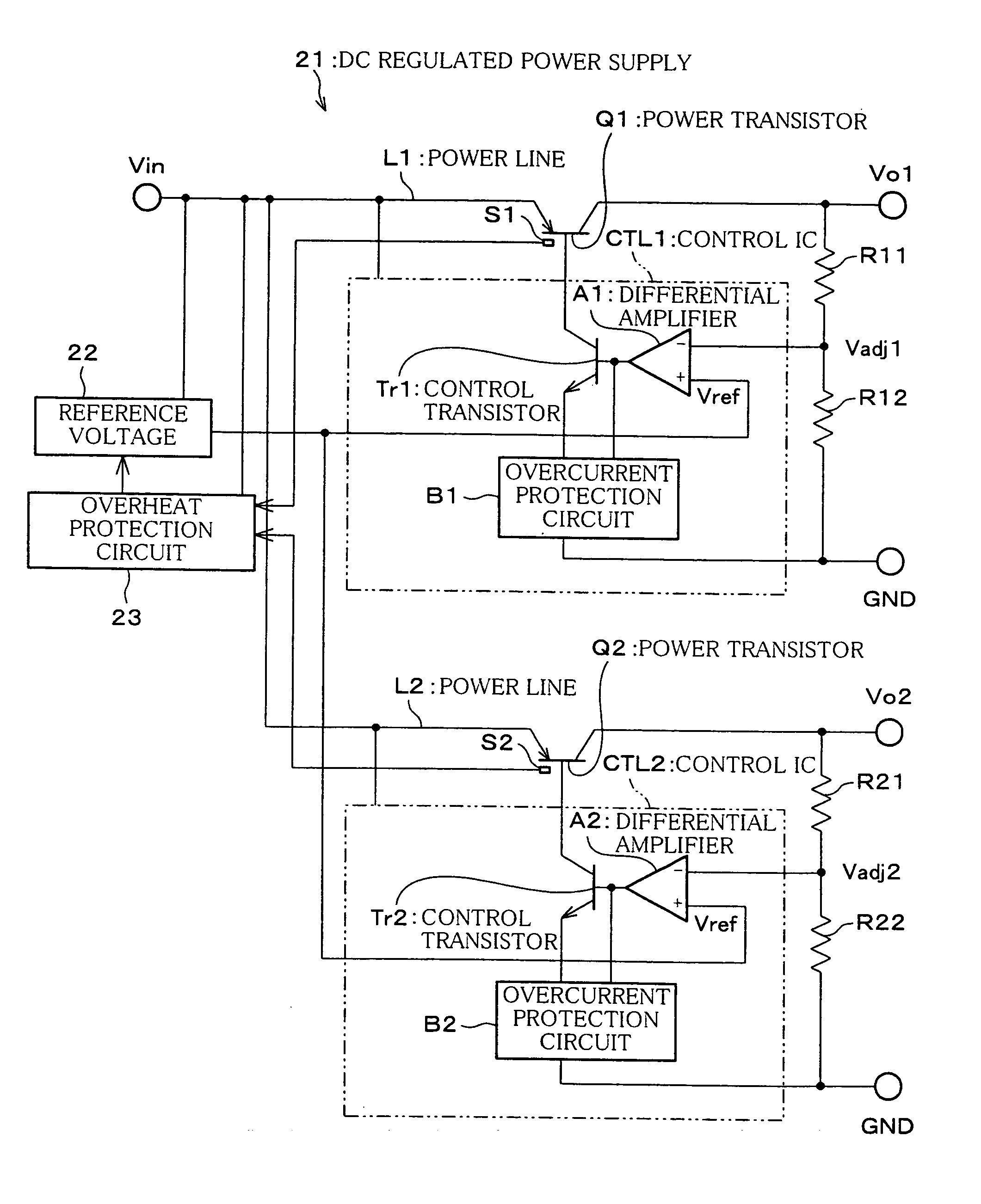
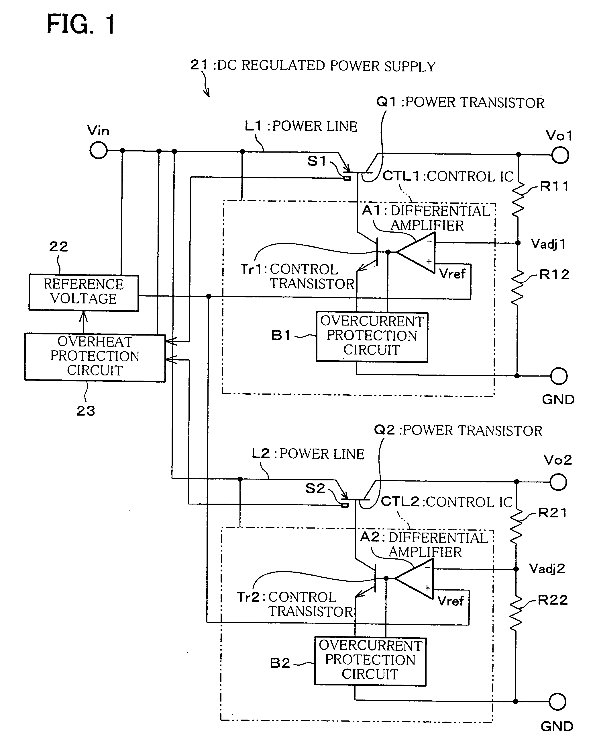
[0036]FIG. 1 is a block diagram illustrating an electrical structure of a DC regulated power supply 21 of the First Embodiment of the present invention. The DC regulated power supply 21 is a regulated power supply of a dropper type, in which output voltages Vo1, Vo2 of two systems are produced from a common input voltage Vin.

[0037] The output voltages Vo1, Vo2 of two systems may have the same level or different levels. Likewise, the current capacitance may be the same or different. Further, the number of systems is not just limited to two, and outputs of three or more systems may be used.

[0038] Power transistors Q1, Q2 are serially and respectively connected to power lines L1, L2 that connect a common power supply (not shown) to their respective loads. Control ICs CTL1, CTL2 are provided to control the base currents of the power transistors Q1, Q2, respectively. By controlling the base cur...

second embodiment

[0046] The following describes another embodiment of the present invention.

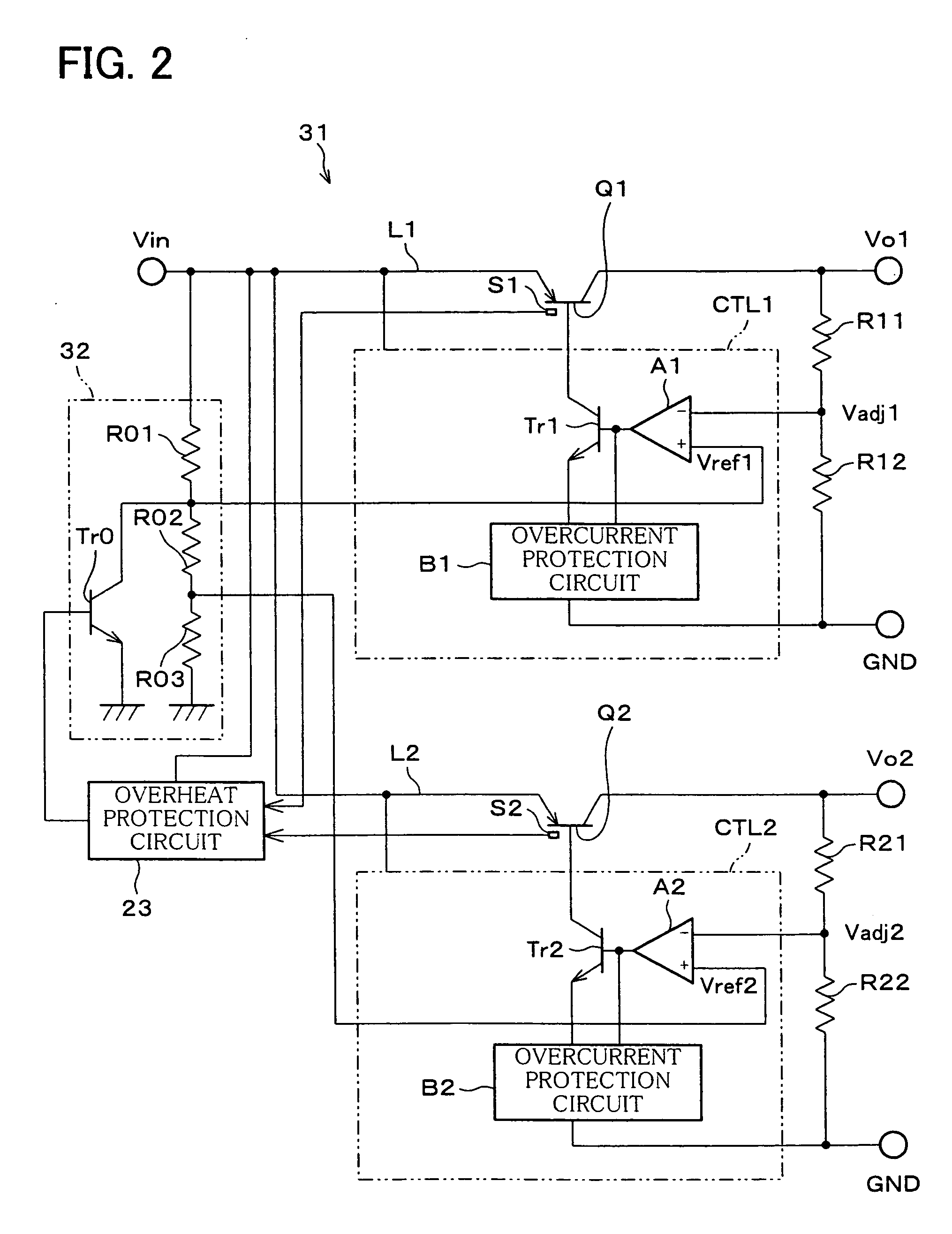
[0047]FIG. 2 is a block diagram illustrating an electrical structure of a DC regulated power supply 31 of the Second Embodiment of the present invention. The DC regulated power supply 31 is similar to the DC regulated power supply 21, and accordingly corresponding elements are given the same reference numerals and explanations thereof are omitted here.

[0048] What should be noted about the DC regulated power supply 31 is that a reference voltage source 32 generates two reference voltages Vref1, Vref2, and supplies these voltages respectively to differential amplifiers A1, A2. In the example of FIG. 2, the voltages produced by dividing the input voltage Vin through resistors R01, R02, and R03 are Vref1 and Vref2, which are related to each other by Vref1>Vref2.

[0049] Further, in the reference voltage source 32, a control transistor Tr0 is provided parallel to the resistors R02, R03. The control transistor Tr0...

third embodiment

[0053] The following describes an electrical structure of a DC regulated power supply 41 of the Third Embodiment of the present invention. The DC regulated power supply 41 is similar to the foregoing DC regulated power supply 21, and accordingly corresponding elements are given the same reference numerals and explanations thereof are omitted here.

[0054] What should be noted about the DC regulated power supply 41 is that switches SW1, SW2 are respectively provided for the lines of reference voltage Vref supplied to the differential amplifiers A1, A2 from the reference voltage source 22, and that the switches SW1, SW2 are controlled by the overheat protection circuit 43. Further, in addition to controlling the switches SW1, SW2, the overheat protection circuit 43 in the DC regulated power supply 43 is provided with a delay circuit, so as to vary ON timings of the switches SW1, SW2 when reverting to a normal state from an overheated state.

[0055] Thus, detecting an overheated state, t...


PUM


Abstract

A DC regulated power supply includes: a power transistor provided for each output of a plurality of systems; a control IC, which compares a feedback value of an output voltage and a reference voltage from a reference voltage source, and controls a base current of the power transistor according to a difference of the feedback value and the reference voltage, so as to regulate the output voltage; and an overheat protection circuit, which lowers the reference voltage of the reference voltage source upon detecting an overheated state in the power transistor. The DC regulated power supply is able to simultaneously suppress transistor base currents of different systems and eliminate regulation malfunctions in the overheat protection operation, thereby suppressing fluctuations of output voltage.

Description

CROSS-REFERENCE TO RELATED APPLICATION [0001] This application is a Divisional of co-pending application Ser. No. 10 / 608,565, filed on Jun. 30, 2003, the entire contents of which are hereby incorporated by reference and for which priority is claimed under 35 U.S.C. § 120.FIELD OF THE INVENTION [0002] The present invention relates to a DC regulated power supply of a dropper-type, known as a series regulator, and particularly to a structure for the protection against overheating in such a DC regulated power supply with outputs of plural systems. BACKGROUND OF THE INVENTION [0003]FIG. 6 is a block diagram illustrating a basic electrical structure of a dropper-type DC regulated power supply 1. The DC regulated power supply 1 is a three-terminal regulator with a single output, in which a power transistor q is interposed in series on a power line 1 that connects a power supply with a load (neither is shown). The base current of the power transistor q is controlled by a control IC ctl. In ...

Claims


Application Information

Patent Timeline
Patent Type & Authority Applications(United States)
IPC IPC(8): G05F1/56H02J1/08H03K17/08H03K17/082H03K17/62
CPCH02J1/08H03K2017/0806H03K17/6271H03K17/0826
Inventor YAMAMOTO, SHINZOU
Owner SHARP KK
Learn More