
Circuits capable of trickle precharge and/or trickle discharge

a charging circuit and circuit technology, applied in safety/protection circuits, secondary cells servicing/maintenance, instruments, etc., can solve the problems of large pre-charging current, large pre-charging current, and high cost of increasing pcb area

Active Publication Date: 2005-09-29
O2 MICRO INT LTD
View PDF3 Cites 46 Cited by
  • Summary
  • Abstract
  • Description
  • Claims
  • Application Information

AI Technical Summary

Benefits of technology

[0054] Advantageously, trickle precharge current control, as described in numerous embodiments herein, can be utilized during a CV time period where trickle precharge circuitry may be capable of generating a trickle charge current based on the cell voltage. In this manner, the CV charge current taper does not need to rely on the charger regulated voltage Vov. Therefore, advantageously, the present disclosure provides several embodiments which may obviate the need for an expensive, accurate voltage regulation charger. Indeed, a simple AC adapter can be used to charge the lithium ion battery. Because in CV charge period, even the charger cannot hold the constant voltage to Vov, but the charge current is limited to the pre-programmed trickle current value, which is determined based on the cell voltage. So, over charging won't happen. This charge current limitation can be used as a secondary over-voltage protection (by setting the current limit slightly above the actual observed current for the desired VUV), and / or as the primary over-voltage protection (by regulating the charge current until the exact desired VUV is obtained).

Problems solved by technology

If, for example, the charging output is larger than VOV then over-charging the battery may occur, which may present safety issues with LiIon batteries.
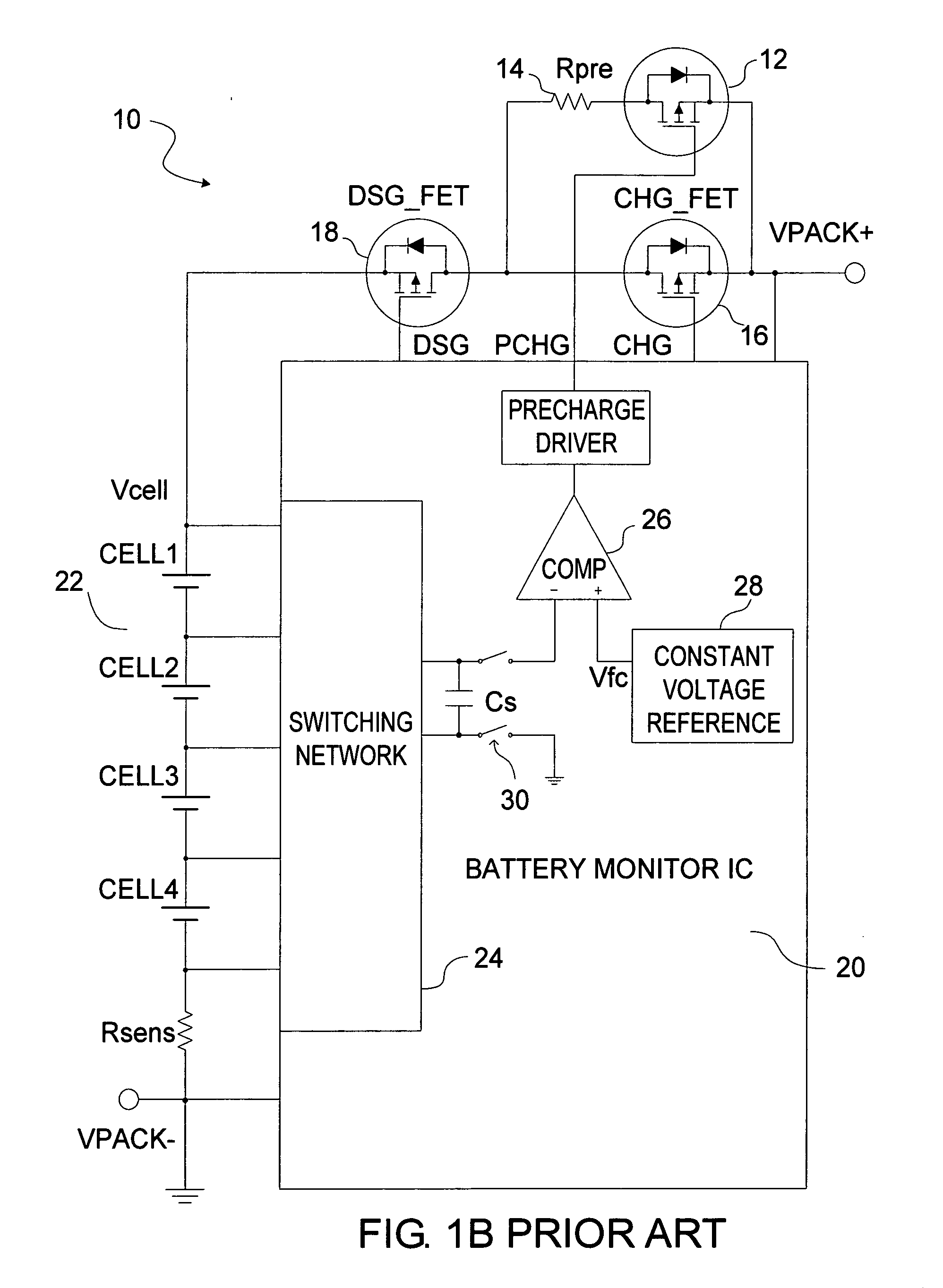
However, one drawback of the topology depicted in FIG. 1 is that an extra power MOSFET (i.e., MOSFET 12) and resistor 14 are required, which are expensive and increase PCB area.
Additionally, with this topology, the lower the cell voltage results in a larger precharging current.
Also, precharging current decreases with the increasing of cell voltage, which translates into longer time to finish precharging.

Method used


Image

  • Circuits capable of trickle precharge and/or trickle discharge
  • Circuits capable of trickle precharge and/or trickle discharge
  • Circuits capable of trickle precharge and/or trickle discharge

Examples


Embodiment Construction

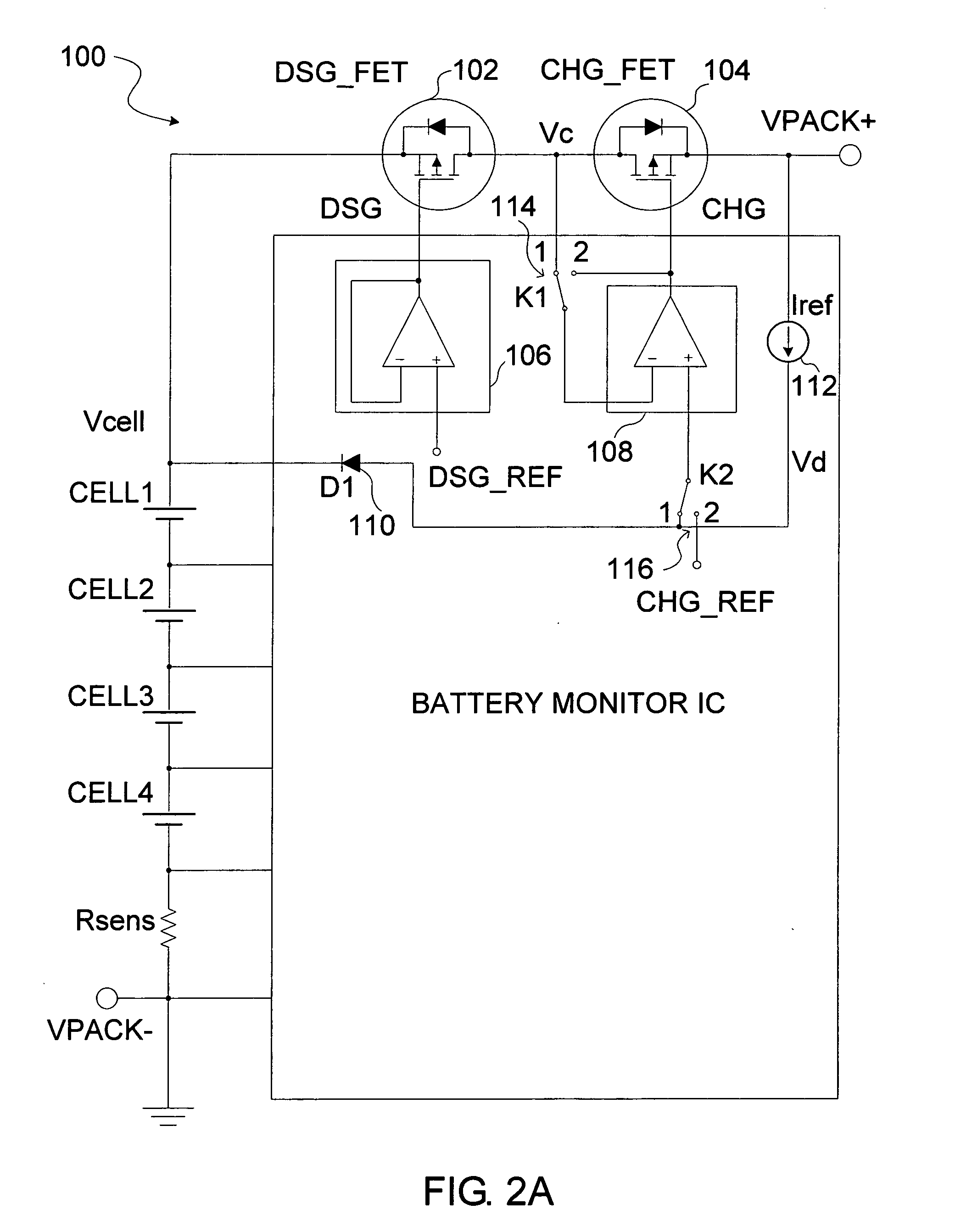
[0020]FIG. 2A depicts one exemplary trickle precharge topology 100 according to the present invention. In this embodiment, two FETs (charge FET CHG_FET and discharge FET DSG_FET) may be used. In this embodiment, the charge FET 104 and discharge FET 102 may be placed back-to-back in series in the manner depicted and as understood in the art. In a trickle precharge mode, the discharge FET 102 may be off (non-conducting), but current may still pass through its body diode to the battery cells if charge FET(CHG_FET) is on (conducting). If CHG_FET is off, then no current flows from or into the battery cells.

[0021] Besides two MOSFETs, this topology 100 may also include a reference diode D11110, discharge driver 106, charger driver 108, and reference current source Iref 112. The charge driver 108 and discharge driver 106 may each comprise respective comparators. In a regular charge mode, switches K1 and K2 (114 and 116) are set to position 2. In this position, the charge driving voltage C...


PUM


Abstract

Battery charging circuitry and systems are provided. One embodiment may include at least one switch having a full conduction state and a controllable conduction state and switch control circuitry capable of sensing a condition. The switch control circuitry may further be capable of generating at least one control signal capable of controlling the conduction state of the switch based on, at least in part, the sensed condition.

Description

[0001] The present application claims priority to U.S. Provisional Application Ser. No. 60 / 556,254, filed Mar. 25, 2004, and hereby incorporated by reference in its entirety.1. FIELD OF THE INVENTION [0002] The present disclosure relates to battery charging circuits, and more particularly, to battery charging circuits capable of trickle precharge and / or trickle discharge. Utility for the present invention can be found in battery charging systems for portable electronic devices, for example, laptop computers, PDAs, cell phones, and / or any type of electronic device having a rechargeable battery. 2. BACKGROUND OF THE INVENTION [0003] Rechargeable batteries, especially lithium ion batteries, need to precharge (recovery-charge) from deeply discharged status to avoid stressing the depleted batteries. When a rechargeable battery is deeply discharged and its cell voltage lower than a threshold voltage VUV, it cannot be directly charged using large charging current. Instead, a pre-charge mod...

Claims


Application Information

Patent Timeline
IPC IPC(8): H02J7/04G05F1/46H01M10/44H02J7/00H02J7/02
CPCH02J7/0075H02J7/0031H02J7/00302H02J7/00308H02J7/0069
Inventor DENNING, BRUCE S.LI, GUOXINGLIU, LIUSHENG
Owner O2 MICRO INT LTD
Learn More