
Anti-vibration mount apparatus, exposure apparatus, and device manufacturing method

a technology of anti-vibration and mounting apparatus, applied in the direction of mechanical apparatus, machine supports, shock absorbers, etc., can solve the problems of reducing the control resolution, affecting the control effect, so as to achieve high-precision control

Inactive Publication Date: 2005-09-29
CANON KK
View PDF10 Cites 9 Cited by
  • Summary
  • Abstract
  • Description
  • Claims
  • Application Information

AI Technical Summary

Benefits of technology

[0024] The present invention can provide an anti-vibration mount technique capable of high-precision control.

Problems solved by technology

That is, if a thick diaphragm is used, the control pressure greatly changes by a decrease in control resolution, an increase in hysteresis, and a change in temperature.
When satisfactory airtightness is ensured, smooth sliding is not achieved, and the pressure precision and response characteristic degrade.
Thus, it is difficult to increase the pressure control resolution (first problem).
The opening of the gas exhaust path changes, and the set pressure changes along with this (second problem).
In the electropneumatic converter, satisfactory linearity of the control pressure to a command value cannot be obtained in switching from supply to exhaust of gas with respect to the secondary chamber or reverse switching.
As a result, the control pressure deviates from a target pressure (third problem).
These problems arise when the above-described electropneumatic converter is applied to a precision machinery such as an anti-vibration / vibration suppression mount apparatus for a semiconductor manufacturing apparatus.

Method used


Image

  • Anti-vibration mount apparatus, exposure apparatus, and device manufacturing method
  • Anti-vibration mount apparatus, exposure apparatus, and device manufacturing method
  • Anti-vibration mount apparatus, exposure apparatus, and device manufacturing method

Examples


Embodiment Construction

[0036] A preferred embodiment of the present invention will be described below with reference to the accompanying drawings.

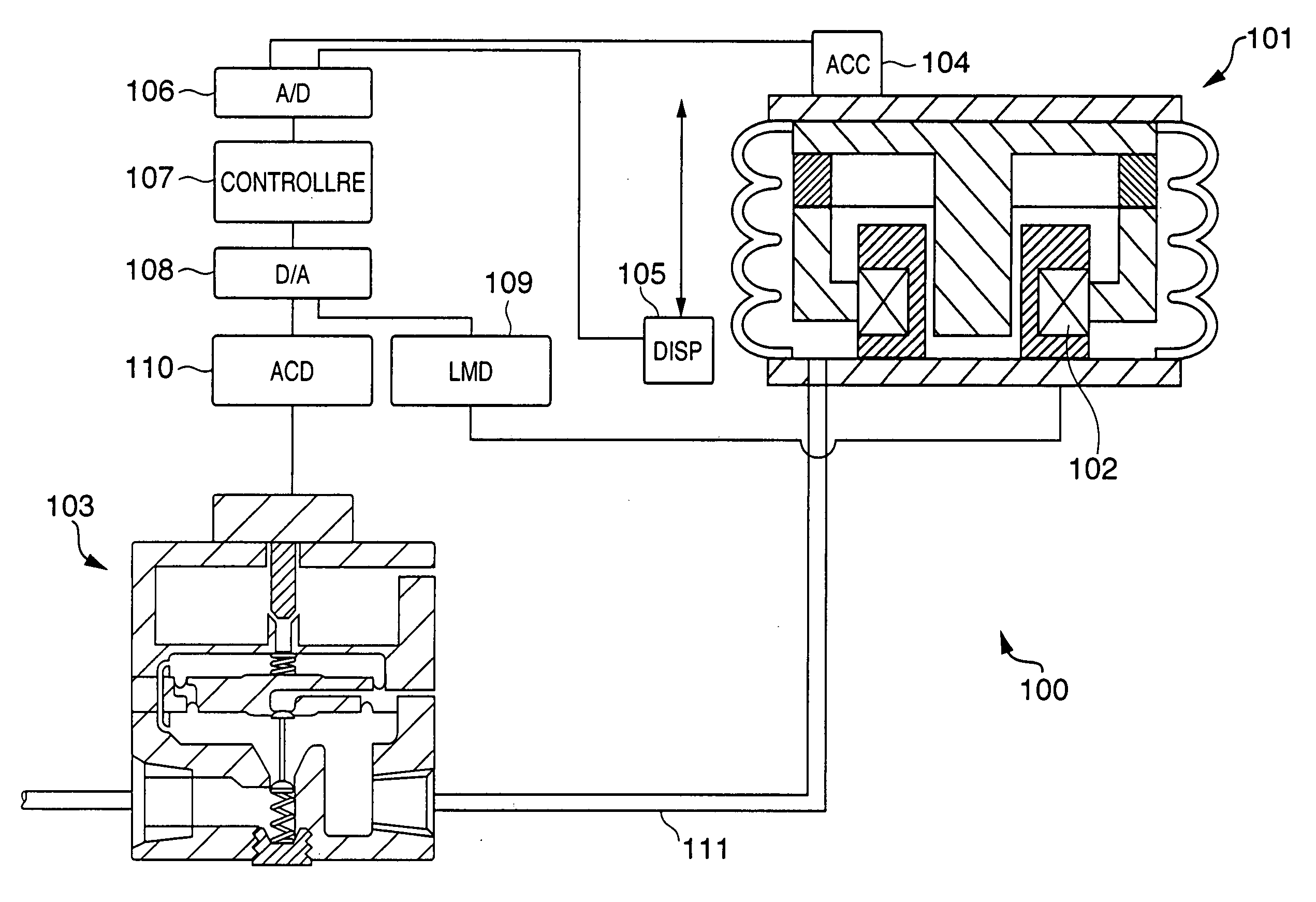
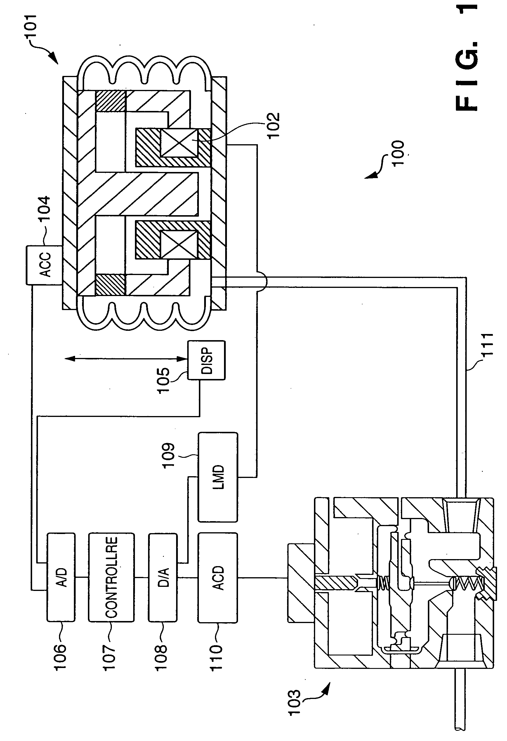
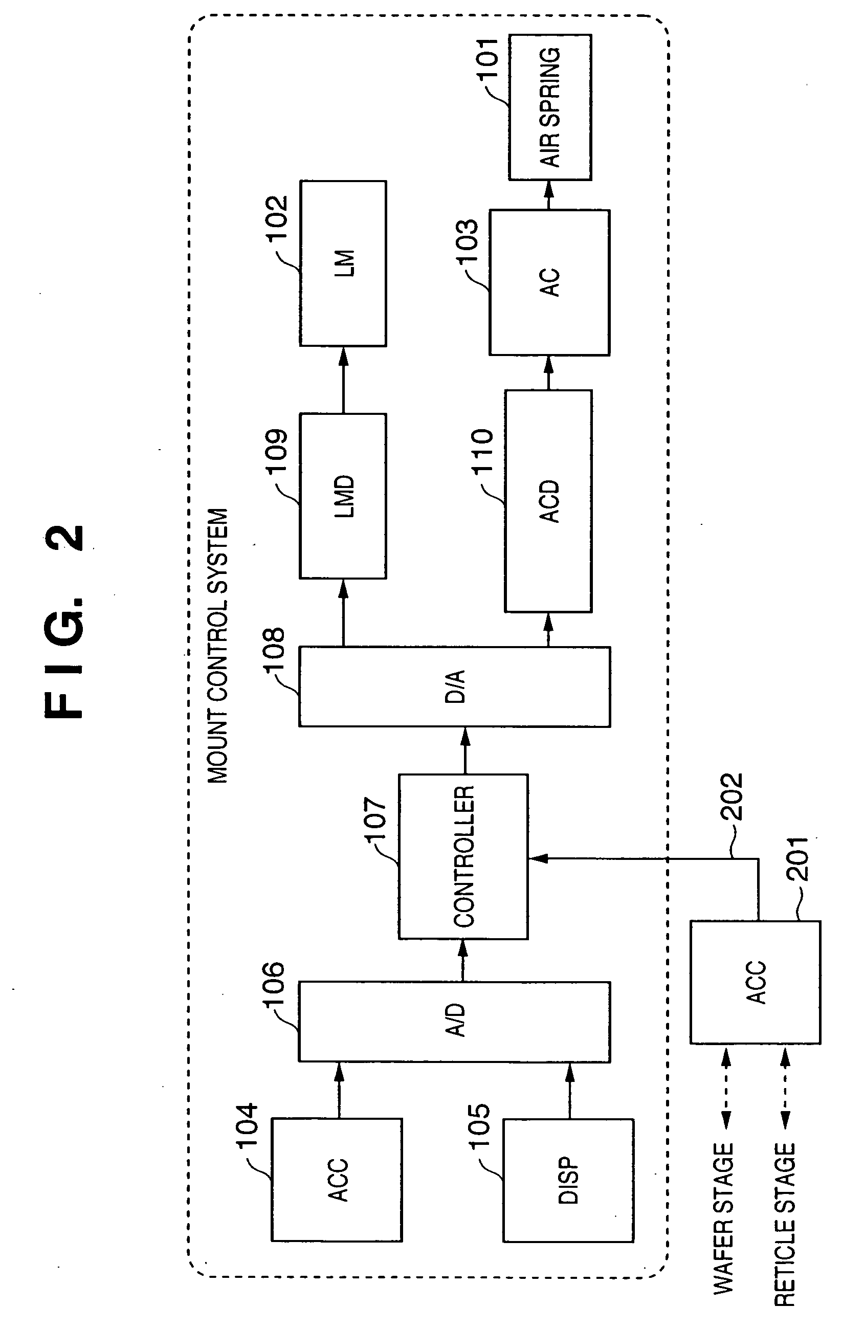
[0037]FIG. 1 is a view schematically showing the arrangement of an anti-vibration mount apparatus according to the preferred embodiment of the present invention. An anti-vibration mount apparatus 100 is typically installed between the floor and a supported structure. The anti-vibration mount apparatus 100 comprises, for example, an air spring 101, linear motor (linear motion type electromagnetic actuator) 102, pressure controller 103, accelerometer 104, displacement gauge 105, A / D converter 106, controller 107, D / A converter 108, linear motor driver 109, and pressure controller driver 110. The anti-vibration mount apparatus 100 drives the linear motor 102 and controls the pressure in the air spring 101 on the basis of the displacement and acceleration of the output end of the anti-vibration mount apparatus 100 or those of the supported structure coupled to the ...


PUM


Abstract

An anti-vibration mount apparatus which suppresses vibration of a structure is disclosed. The apparatus comprises a gas spring which supports the structure, and a controller which controls an internal pressure of the gas spring. The controller comprises a primary chamber which communicates with a pressure source, a secondary chamber which communicates with the gas spring, a back-pressure chamber which communicates with the secondary chamber, a back-pressure control mechanism which has a nozzle communicating with the back-pressure chamber and a flapper facing the nozzle and controls a pressure in the back-pressure chamber via control of exhaust from the back-pressure chamber by changing a gap between the nozzle and the flapper, and a pressure control mechanism which controls a pressure in the secondary chamber via one of gas supply from the primary chamber to the secondary chamber and gas exhaust from the secondary chamber to outside caused in accordance with a pressure difference between the back-pressure chamber and the secondary chamber. The flapper has a tapered portion facing the nozzle, and the nozzle has a bore widened toward an outlet of the nozzle.

Description

FIELD OF THE INVENTION [0001] The present invention relates to an anti-vibration mount technique applicable to a precision machinery such as an exposure apparatus. BACKGROUND OF THE INVENTION [0002] An anti-vibration mount apparatus is used to remove vibrations of a precision machinery such as an exposure apparatus. Japanese Patent No. 3,219,198 relates to an air spring anti-vibration table. This reference describes an air spring anti-vibration table which comprises an electropneumatic converter for controlling the pneumatic pressure in a pilot room that balances with the pneumatic pressure in an air spring support leg. The air spring anti-vibration table controls the pneumatic pressure in the air spring support leg in accordance with variations in the pneumatic pressure in the pilot room. This anti-vibration table supplies air from a primary pneumatic pressure source to the pilot room by a vibrating valve to raise the pneumatic pressure in the pilot room, and exhausts air via an EX...

Claims


Application Information

Patent Timeline
IPC IPC(8): G03F7/20F15B5/00F16F15/02F16F15/027F16M7/00H01L21/027
CPCF16F15/0275
Inventor HATA, TOMOYASUYANAGISAWA, MICHIOMAEDA, TAKASHISHIBAYAMA, TAKASHI
Owner CANON KK
Learn More