
Scanning probe microscope and measuring method by means of the same

a scanning probe and microscope technology, applied in the direction of instruments, mechanical roughness/irregularity measurements, measurement devices, etc., can solve the problems of sample exposure to air, difficult to adjust the probe to and inability to know the amount of deformation of the preceding analysis pla

Inactive Publication Date: 2005-09-29
HITACHI HIGH TECH SCI CORP
View PDF5 Cites 5 Cited by
  • Summary
  • Abstract
  • Description
  • Claims
  • Application Information

AI Technical Summary

Benefits of technology

[0008] An object of the invention is to provide a scanning probe microscope capable of solving the above problems, radiating light on a sample without moving the sample from the scanning probe microscope and measuring the sample without changing the location of the sample and with controlling the condition under which the sample is placed.
[0015] A scanning probe microscope and a method of measuring a sample by means of the same in accordance with the invention have the following effects.
[0016] In a scanning probe microscope in accordance with the invention, at the time of exposure, detaching an independently detachable cantilever bending amount detecting means from the scanning probe microscope allows the sample to be exposed by means of an exposure light source without blocked by the cantilever bending amount detecting means, so that the sample can be exposed without moving the cantilever and the sample. Accordingly, an exactly same place of the sample can be analyzed before and after exposure. This allows a sample including a substance, which changes its physical characteristic, composition and / or shape due to a photochemical reaction, or a sample including a substance adsorbed on a photocatalyst, to be efficiently measured and analyzed, so that change in physical characteristic, composition and / or shape of the sample can be evaluated.
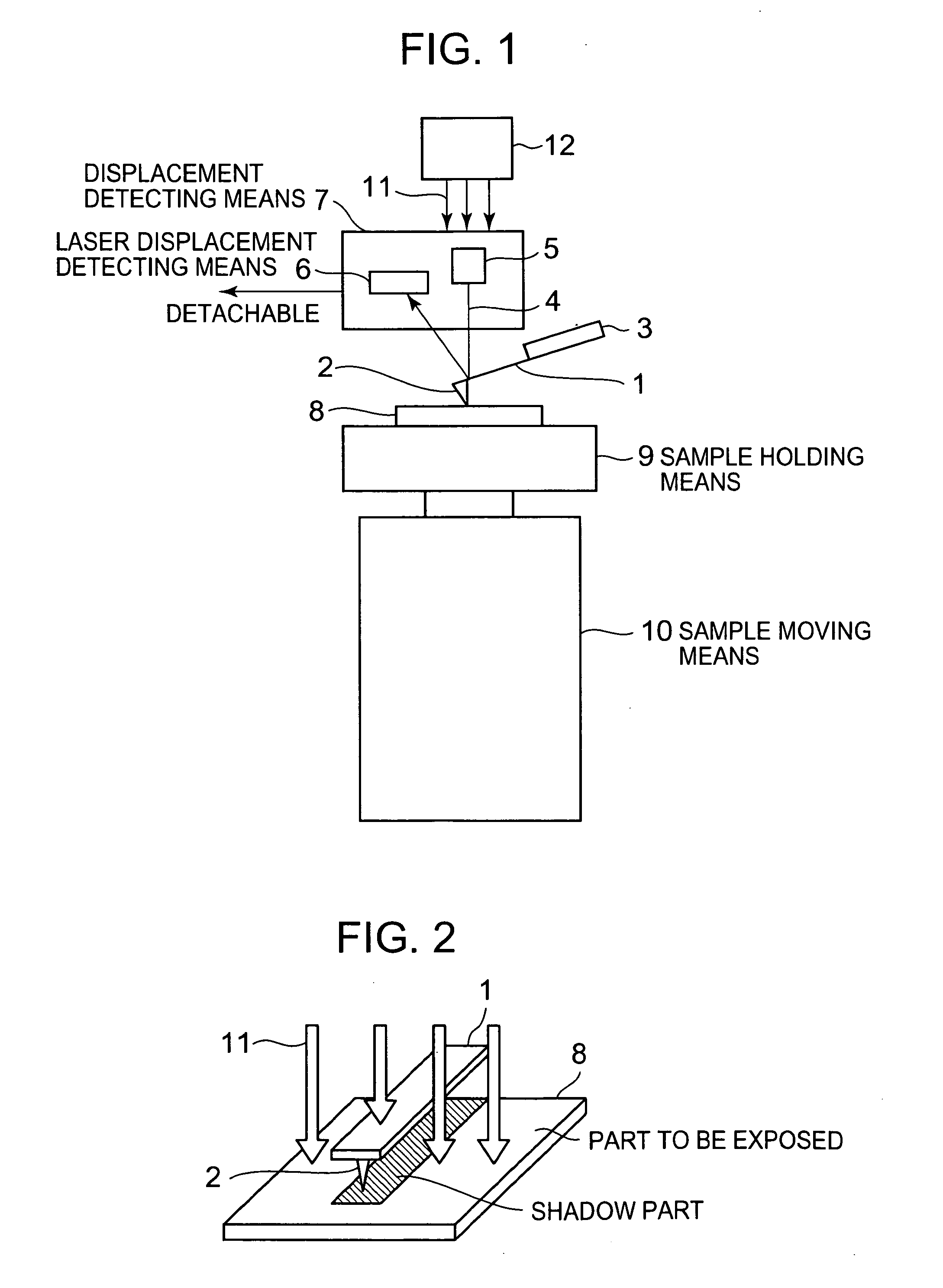
[0017] Further, exposure is carried out under a condition that the cantilever approaches the sample, so that the sample is masked by means of the cantilever while it is exposed. Accordingly, a part of the sample shadowed by the cantilever is not exposed. Moreover, it can be seen on the basis of the shape of the cantilever which place of the sample is exposed. Therefore, measuring an area crossovering an exposed part and an unexposed part after exposure by means of the scanning probe microscope allows a shape and / or a physical characteristic of a surface of the sample before and after exposure to be evaluated by performing measurement once, and furthermore, a boundary between the exposed part and the unexposed part to be measured.

Problems solved by technology

The conventional method includes, however, a step for taking out a sample from the scanning probe microscope, so that there is a problem of having a trouble in taking out and re-introducing the sample.
Further, the scanning probe microscope has a problem that it is difficult to adjust a probe to a preceding analysis place when the taken-out sample is introduced again.
Moreover, there is another problem that, in the case of deformation such as a bend or curing contraction due to a photochemical reaction, an amount of deformation of the preceding analysis place cannot be known even when the probe can be adjusted to the place.
The conventional method, however, has a problem that the sample is exposed to the air when taken out from and re-introduced into the scanning probe microscope.

Method used


Image

  • Scanning probe microscope and measuring method by means of the same
  • Scanning probe microscope and measuring method by means of the same
  • Scanning probe microscope and measuring method by means of the same

Examples


embodiment 1

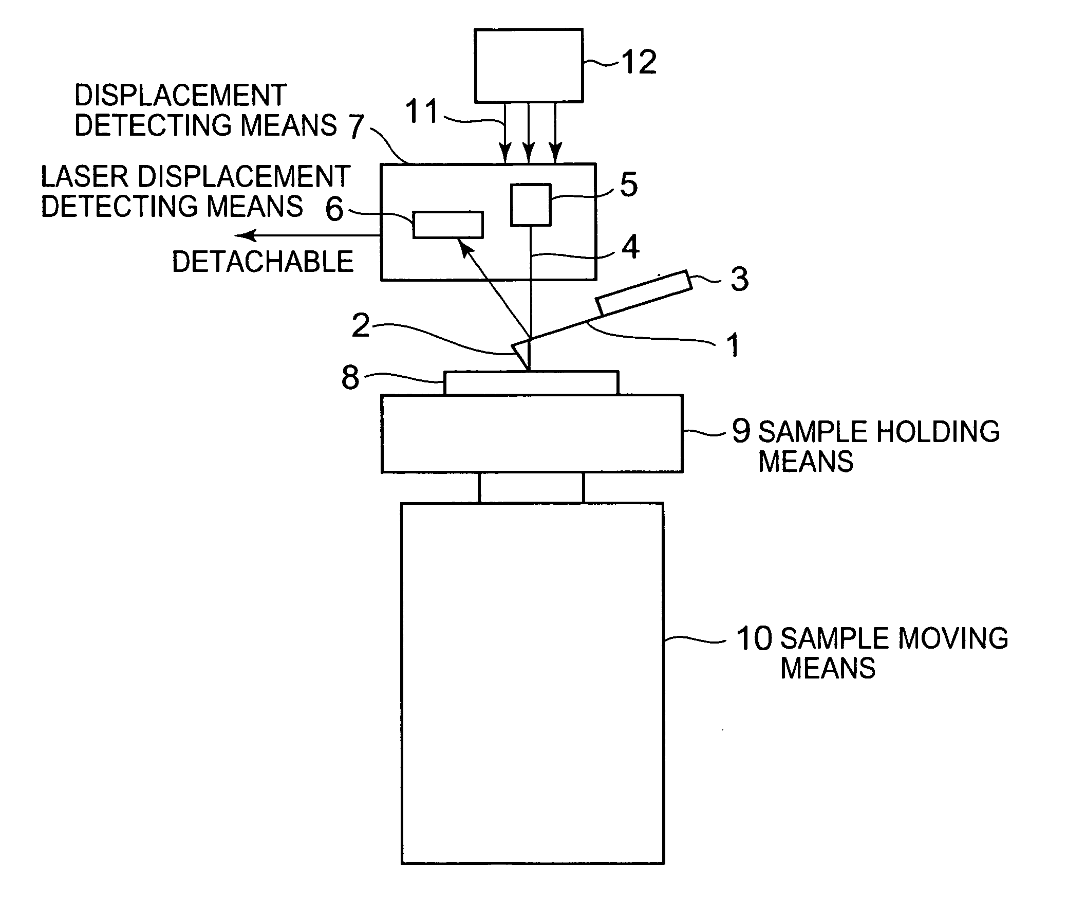
[0023]FIG. 1 is a schematic view showing a structure of a scanning probe microscope in a first embodiment of the invention.

[0024] In FIG. 1, a cantilever 1 is formed of silicon or silicon nitride, has a shape of about 200 μm in length, about 40 μm in width and about 3 μm in thickness and is mounted to a cantilever holder 3. On a top end of the cantilever 1, provided is a minute probe 2, which is produced by etching and is about 3 to 7 μm in height and whose radius at the top end thereof is about 10 nm.

[0025] A laser beam source 5 for radiating a laser beam 4 and laser displacement detecting means 6 are fixedly provided as cantilever bending amount detecting means 7 independently from a sample and the cantilever so as to be detachable without moving the sample and the cantilever. The laser beam 4 is radiated on the cantilever 1. The reflected laser beam from the cantilever 1 reaches the laser displacement detecting means 6. Detecting the displacement of a position where the reflect...

embodiment 2

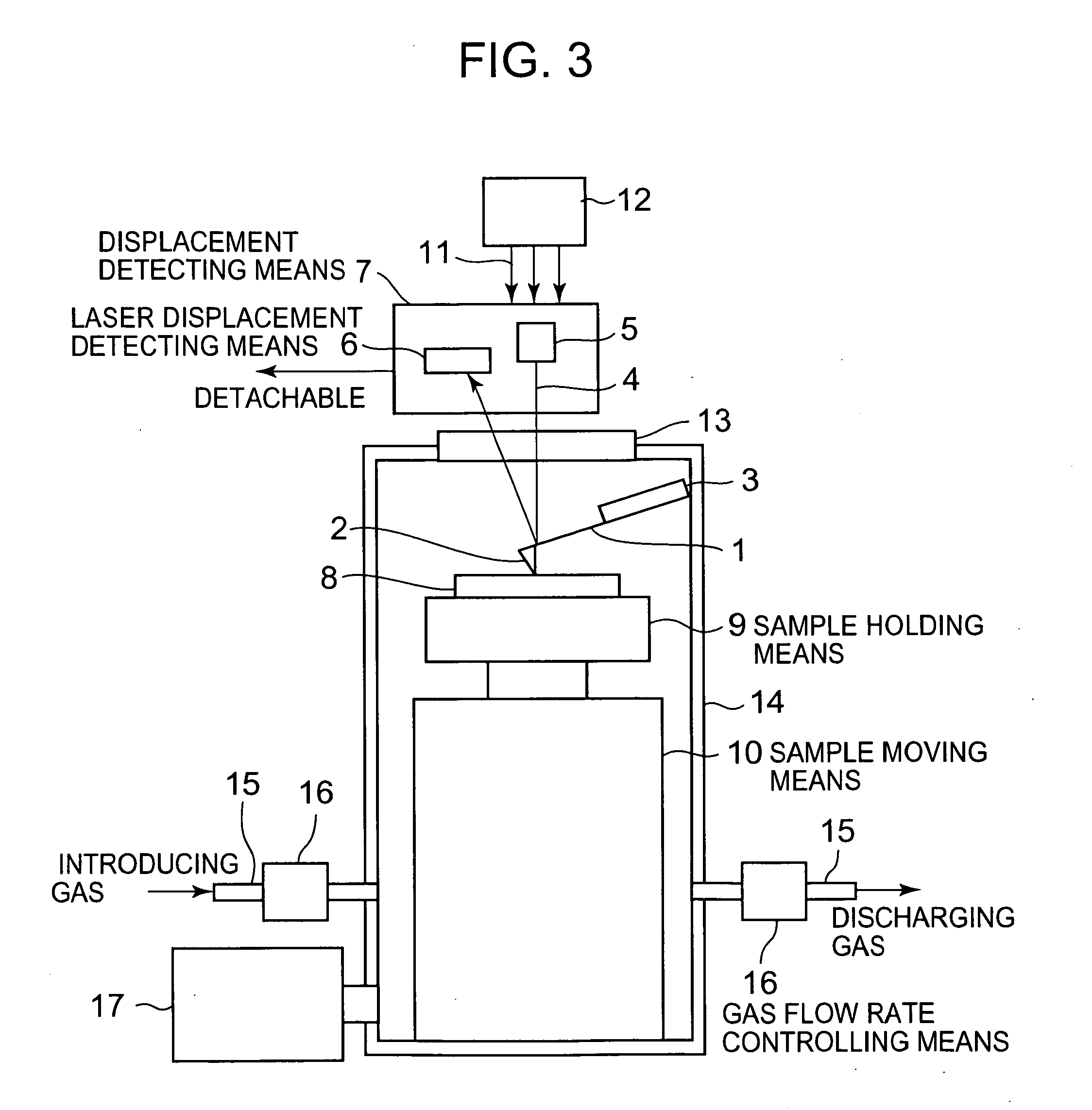
[0031]FIG. 3 is a schematic view showing a structure of a scanning probe microscope in a second embodiment of the invention. Components common to those of Embodiment 1 shown in FIG. 1 are marked with the same reference signs and numerals and detail description thereof is omitted.

[0032] In FIG. 3, a window 13 is made of transparent glass through which light can pass. In the case of using ultraviolet rays as the exposure radiating light, a window made of quartz glass is used to make the ultraviolet rays pass through. An airtight container 14 comprises inside a cantilever 1, a cantilever holder 3, sample holding means 9 and sample moving means 10. It is possible to mount cantilever bending amount detecting means 7 outside the airtight container 14.

[0033] The laser beam 4 radiated from the laser beam source 5 of the cantilever bending amount detecting means 7 is incident on the window 13 to enter the inside of the airtight container 14. The laser beam 4 is then reflected on the cantil...


PUM


Abstract

A scanning probe microscope capable of radiating light on a sample without moving the sample from the scanning probe microscope and measuring the sample with controlling the condition under which the sample is placed and without changing the location of the sample is provided. The scanning probe microscope includes a cantilever having a probe on a top end thereof, sample moving means for moving the sample, detachable cantilever bending amount detecting means for detecting bending amount of the cantilever by means of a laser beam and exposure means for exposing the sample to light from upper side of the cantilever, wherein the cantilever bending amount detecting means is independently detachable when exposure of the sample is carried out.

Description

BACKGROUND OF THE INVENTION [0001] 1. Field of the Invention [0002] The present invention relates to a scanning probe microscope, particularly, a scanning probe microscope for measuring a sample changing its physical characteristic, composition and / or shape by radiation of light, and to a method of measuring a sample by means of the microscope. [0003] 2. Background Art [0004] Conventionally, in order to analyze a substance such as photo-curing resin, which changes its physical characteristic, composition and / or shape by a photochemical reaction, or a substance adsorbed on a photocatalyst, by means of a scanning probe microscope before or after the radiation of light to evaluate the change in physical characteristic, composition and / or shape, used has been a method in which a sample before radiation of light is first analyzed by means of a scanning probe microscope, the sample is once taken out from the scanning probe microscope to be irradiated with light, and then, the sample is ag...

Claims


Application Information

Patent Timeline
IPC IPC(8): G01B5/28G01Q30/20G01Q20/02G01Q30/08G01Q30/10G01Q30/12G01Q30/16G01Q30/18
CPCB82Y35/00G01Q80/00G01Q30/12G01Q20/02
Inventor WATANABE, MASAFUMIANDO, KAZUNORI
Owner HITACHI HIGH TECH SCI CORP
Learn More