Microscope switchable between observation modes

a microscope and observation mode technology, applied in the field of high-performance microscopes, can solve the problems of not being able to switch easily between the two microscopic observation methods to obtain the best optical performance for the detection of molecules, and it is not easy to switch from fluorescence microscopy to total internal reflection fluorescence microscopy, and it is difficult to switch between the two microscopic observation methods at multiple wavelengths

Inactive Publication Date: 2005-09-22
KAWANO YOSHIHIRO
View PDF6 Cites 9 Cited by
  • Summary
  • Abstract
  • Description
  • Claims
  • Application Information

AI Technical Summary

Benefits of technology

[0008] An object of the present invention is to provide a high-performance microscope allowing total internal reflection fluorescence microscopy, fluorescence microscopy and interference reflection microscopy (or reflection contrast microscopy) to be selectively performed by using the same objective.

Problems solved by technology

However, the microscopic observation methods cannot readily be switched from one to another to obtain the best optical performance for detection of molecules. or for observation of living organisms, cells, eggs, etc. with a single microscope.
For example, it has heretofore been not easy to switch from fluorescence microscopy to total internal reflection fluorescence microscopy [for example, see Japanese Patent Application Unexamined Publication (KOKAI) No.
It has also been very difficult to switch between these microscopic observation methods at multiple wavelengths.

Method used


Image

  • Microscope switchable between observation modes
  • Microscope switchable between observation modes
  • Microscope switchable between observation modes

Examples


first embodiment

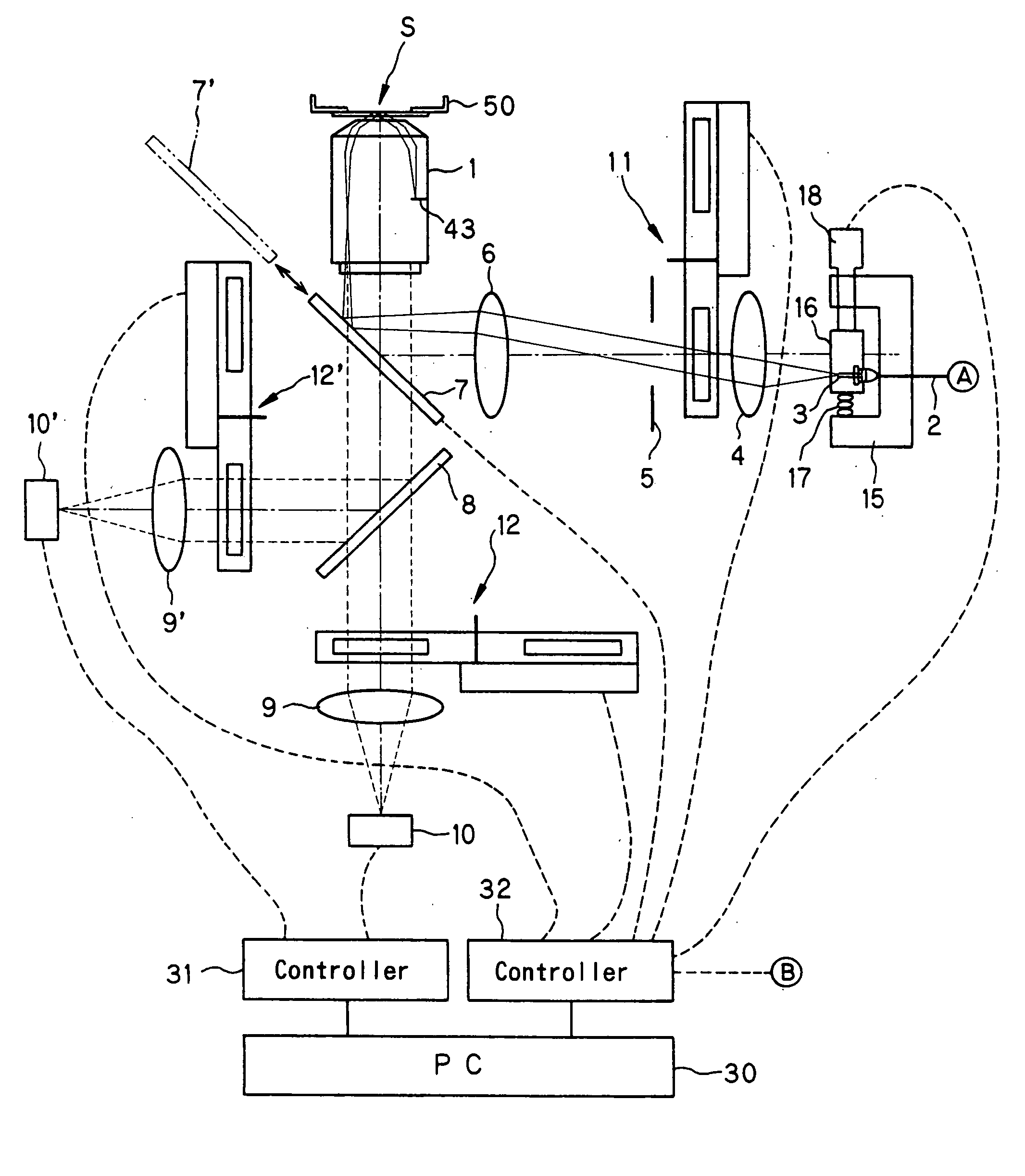
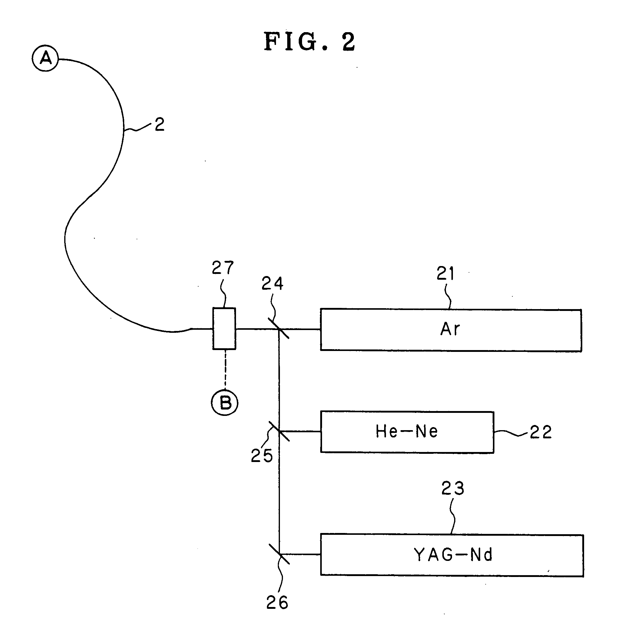
[0030]FIG. 1 shows the arrangement of a microscope system according to the present invention.

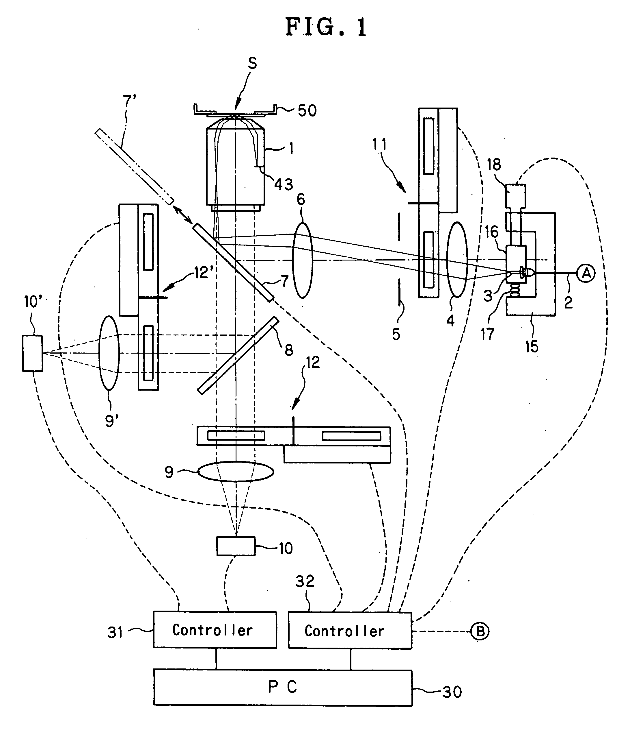
[0031]FIG. 2 shows the arrangement of a light source unit for use in the first embodiment. In this embodiment, a laser beam is used as illuminating light. A laser beam as illuminating light is emitted from an exit end 3 of a single-mode optical fiber 2. The laser light passes through a collector lens 4, a field stop 5 and an illuminating lens 6 and is incident on a dichroic mirror 7 diagonally disposed in the viewing optical path of an inverted microscope. The laser beam reflected by the dichroic mirror 7 enters an objective 1 to illuminate a sample S, which is put in a Petri dish (laboratory dish) 50 placed above the objective 1, from below the sample S. Fluorescence emitted from the sample S enters the objective 1 and then passes through the dichroic mirror 7. The fluorescence further passes through a dichroic mirror 8 and enters an image-forming lens 9 to form a fluorescence image of the ...

fourth embodiment

[0068] Next, the present invention will be described. In this embodiment, the microscope system is arranged to prevent the microscopic image under observation from coming out of focus owing to changes in temperature of the outside air or the like when changes of the sample S with time are observed by various observation methods as stated above.

[0069] In observation of changes of the sample S with time, it is very important to produce a favorable environment for cells by controlling the temperature of the culture solution and the gas. Accordingly, to observe changes of the sample S with time by various observation methods, the objective 1 is mounted on a mechanical component for holding the sample S.

[0070]FIG. 7 is a diagram showing the arrangement of a microscope system according to this embodiment. In FIG. 7, the illuminating and viewing systems of the microscope adopt the arrangement using the white light source 20 as shown in FIG. 5. However, it is also possible to adopt the arr...


PUM


Abstract

A high-performance microscope allows total internal reflection fluorescence microscopy, fluorescence microscopy and interference reflection microscopy (or reflection contrast microscopy) to be selectively performed by using the same objective. The microscope has an objective optical system and an image-forming optical system for imaging light from a sample passing through the objective optical system onto an image pickup device. An optical member is provided in a viewing optical path extending from the objective optical system to the image-forming optical system. The optical member reflects illuminating light from an illuminating optical system so that the illuminating light enters the objective optical system, and allows the light from the sample passing through the objective optical system to pass through the image-forming optical system. The illuminating optical system is provided therein with a mechanism for adjusting an illuminating light collecting position on a pupil plane of the objective optical system in a direction perpendicular to an optical axis. The viewing optical path is provided therein with a wavelength selecting device for selecting an observation wavelength according to the illuminating light collecting position on the pupil plane of the objective optical system.

Description

[0001] This is a division of application Ser. No. 10 / 253,475 filed 25 Sep. 2002, the content of which is incorporated herein by reference in its entirety. [0002] This application claims benefit of Japanese Application No. 2001-290943 filed in Japan on Sep. 25, 2001, the contents of which are incorporated by this reference.BACKGROUND OF THE INVENTION [0003] 1. Field of the Invention [0004] The present invention relates to a microscope switchable between observation modes. More particularly, the present invention relates to a high-performance microscope allowing total internal reflection fluorescence microscopy, fluorescence microscopy and interference reflection microscopy (or reflection contrast microscopy) to be selectively performed by using the same objective. [0005] 2. Discussion of Related Art [0006] Hitherto, various microscopic observation methods have been developed. However, the microscopic observation methods cannot readily be switched from one to another to obtain the bes...

Claims


Application Information

Patent Timeline
Patent Type & Authority Applications(United States)
IPC IPC(8): G02B21/00G02B26/00G02B21/02G02B21/06G02B21/08G02B21/10G02B21/18G02B21/36G02B27/00
CPCG02B21/002G02B21/02G02B21/082G02B21/18G02B2207/113G02B21/365G02B27/0018G02B21/16G02B21/361
Inventor KAWANO, YOSHIHIRO
Owner KAWANO YOSHIHIRO
Why Eureka
Try Eureka