Optical displacement measurement device

Active Publication Date: 2005-09-22
MITUTOYO CORP
View PDF7 Cites 4 Cited by
  • Summary
  • Abstract
  • Description
  • Claims
  • Application Information

AI Technical Summary

Benefits of technology

[0028] Still further, the optical system may comprise a beam splitter for splitting a collimated beam from the light source and advancing light of S polarized component towards the object; a quarter-wavelength retardation plate for converting the light of S polarized component advancing from the beam splitter into light of circular polarization before a resultant light advances toward the object, and for converting light of circular polarization reflected from the object into light of P polarized component before a resultant light returns to the beam splitter; and an objective lens having a conical shape and provided between the quarter-wavelength retardation plate and the object. In the optical system, an image formed by the light of P polarized component which returns from the object and passes through the quarter-wavelength retardation plate and the beam splitter may be detected using the detection section. With this arrangement, the light advancing toward the object and the light reflected from the object and forming an image for detection can be separated. This makes it more easier to measure displacement of the image.
[0029] As described above, with an optical displacement measurement device of the present invention, displacement of an object can be readily measured in the novel manner described herein.

Problems solved by technology

This method, however, suffers from a very narrow measurable range as a highly accurate detection range is limited to an area near the focal point.
In an auto-focus operation, however, high speed measurement is not readily achievable should the surface of an object have discontinuous displacement due to a step, for example, as, in such a case, the lens would lose its direction to follow and another search operation may become necessary.
As described above, although a variety of non-contact displacement measurement methods have been proposed, these methods in conjunction with the advantages they provide, have remaining problems in view of their ability to obtain high precision, high speed, price reduction, usability, increased reliability, and so forth.

Method used


Image

  • Optical displacement measurement device
  • Optical displacement measurement device
  • Optical displacement measurement device

Examples


Embodiment Construction

[0039] In the following, an embodiment of the present invention will be described in detailed with reference to the accompanying drawings.

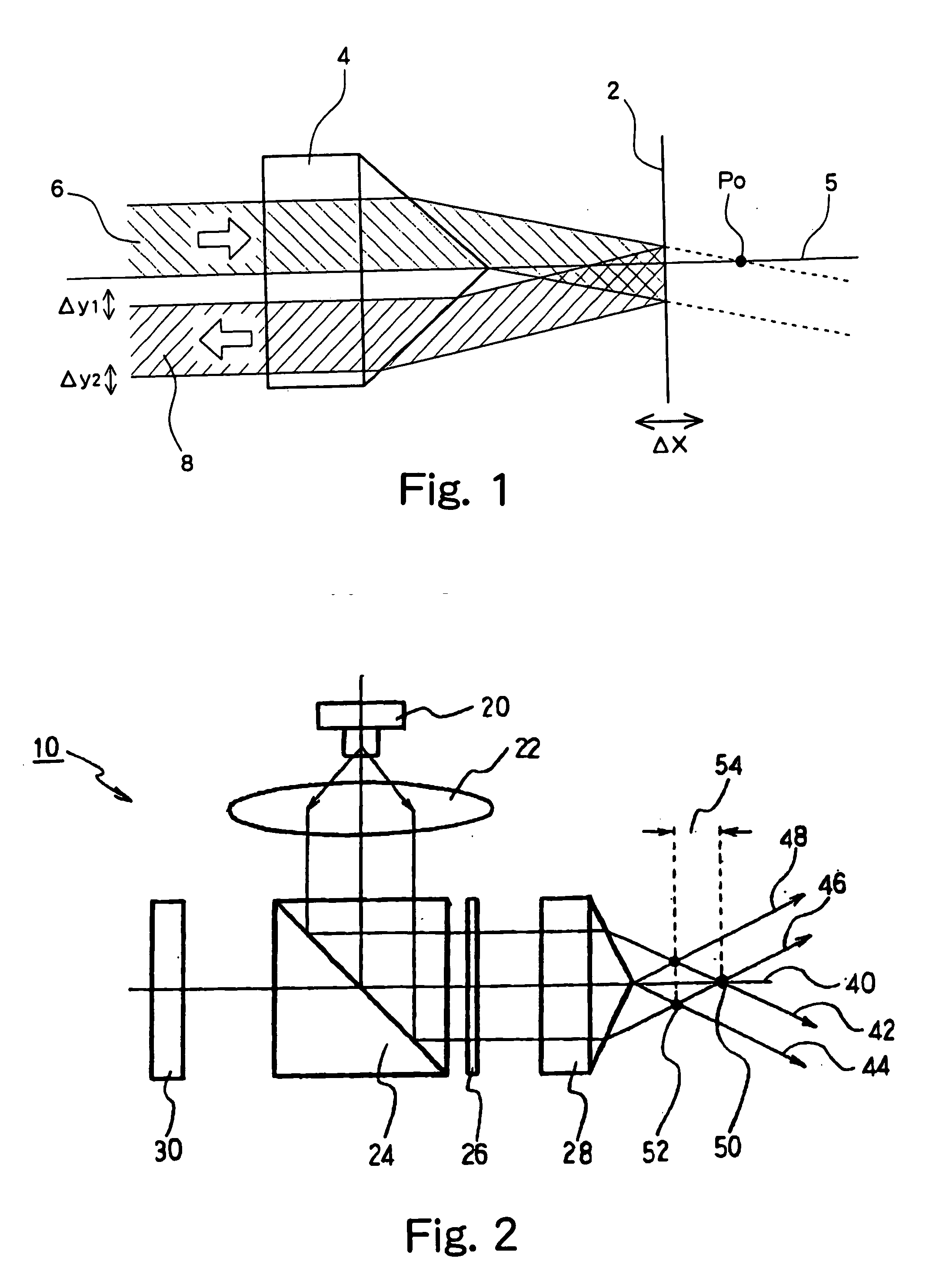
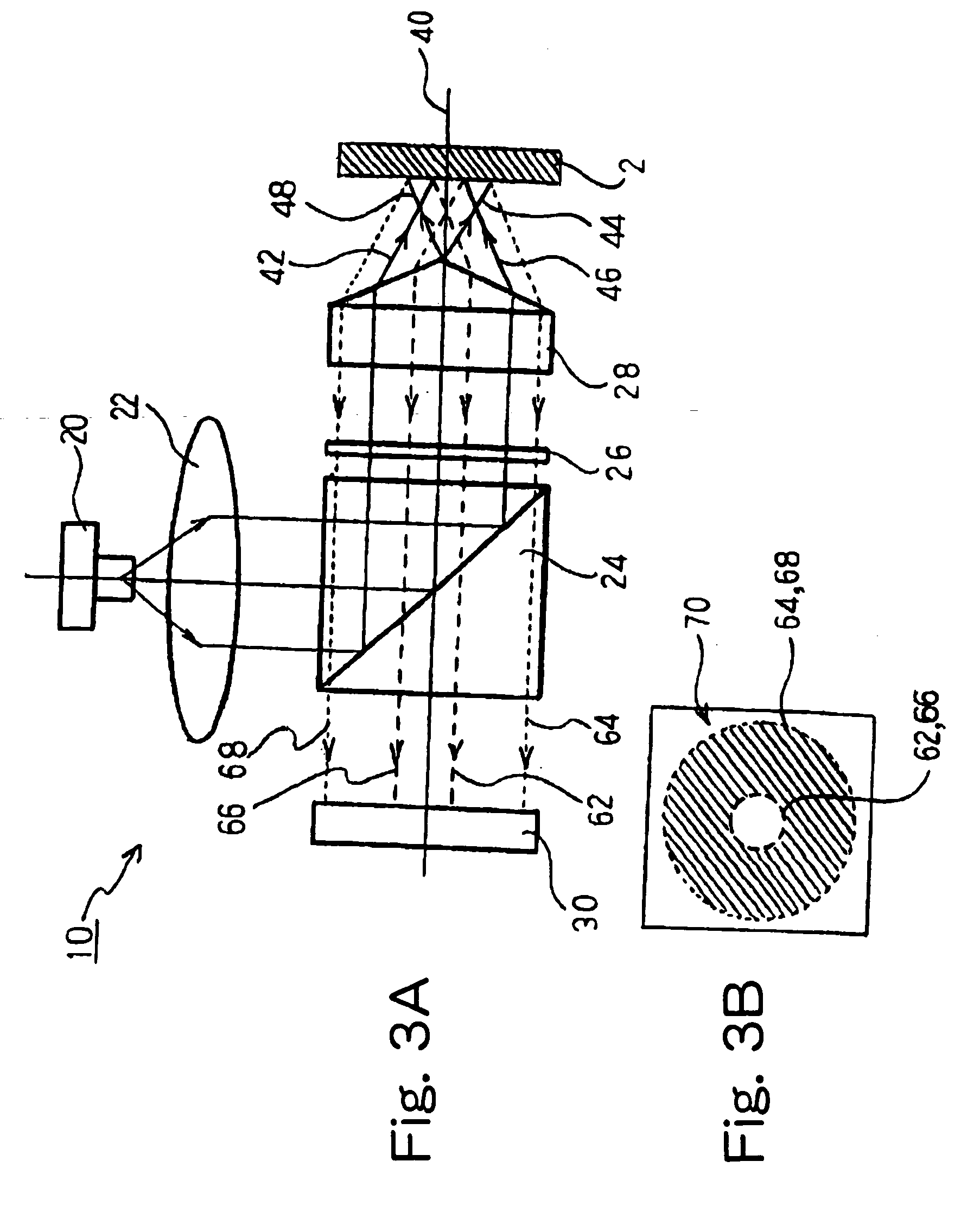
[0040]FIG. 2 shows a structure of an optical displacement measurement device 10, which mainly includes a light source 20, an optical system containing a conical objective lens 28, and a detection section 30 for detecting an image of an object. It should be noted that, to simplify understanding, an enclosure for positioning and supporting these members and a displacement amount calculation section connected to the detection section 30, as well as certain other components, are not shown in FIG. 2.

[0041] In FIG. 2, the light source 20 emits light to irradiate an object placed in front of the objective lens 28. The light source 20 may be formed using a semiconductor laser or the like. A light emission diode and any other light emitting element may be usable as the light source 20, as long as it is optically stable.

[0042] A collimate lens 22 is plac...


PUM


Abstract

An optical displacement measurement device for introducing light from a light source to an object through an optical system having an objective lens and for detecting light reflected from the object by a detection section to thereby measure a displacement of the object relative to the objective lens. In the optical displacement measurement device, the objective lens is a conical lens for advancing the light toward the object and for receiving light reflected from the object to direct to the detection section, and the displacement of the object relative to the objective lens is measured in consideration of the property that a shape of an detected image detected by the detection section varies depending on the displacement of the object relative to the objective lens.

Description

BACKGROUND OF THE INVENTION [0001] 1. Field of the Invention [0002] The present invention relates to an optical displacement measurement device, and in particular to an optical displacement measurement device for directing light from a light source toward an object through an optical system which includes an objective lens, and detecting light reflected from the object using a detection section to thereby measure a displacement of the object relative to the objective lens. [0003] 2. Description of the Related Art [0004] For non-contact measurement of an object displacement, optical probe methods, such as those described by Toyohiko Yatagai in “Applied Optics, Introduction to Optical Measurement” (4th version, Maruzen Co., Ltd., Mar. 15, 1992, p 120-124), are known. The optical probe methods described therein include a critical angle method, an astigmatic method, a knife edge method, a heterodyne method, and others. In any of these methods, a minute spot is caused to be formed on the...

Claims


Application Information

Patent Timeline
IPC IPC(8): G01B11/00G01B11/02G01C3/02G01C3/06G01C3/08G01S7/481
CPCG01B11/026G01S7/4812G01C3/08
Inventor IWAMOTO, TADASHITANIMURA, YOSHIHISA
Owner MITUTOYO CORP
Why Eureka
Try Eureka