
Ink jet printer

a jet printer and ink technology, applied in the direction of printing, thin material processing, article separation, etc., can solve the problems of deterioration of the performance of discharging ink drips from the nozzle, rising of the viscosity of the ink in the nozzle, and the inability to discharge ink drips

Inactive Publication Date: 2005-09-22
SEIKO EPSON CORP
View PDF7 Cites 21 Cited by
  • Summary
  • Abstract
  • Description
  • Claims
  • Application Information

AI Technical Summary

Benefits of technology

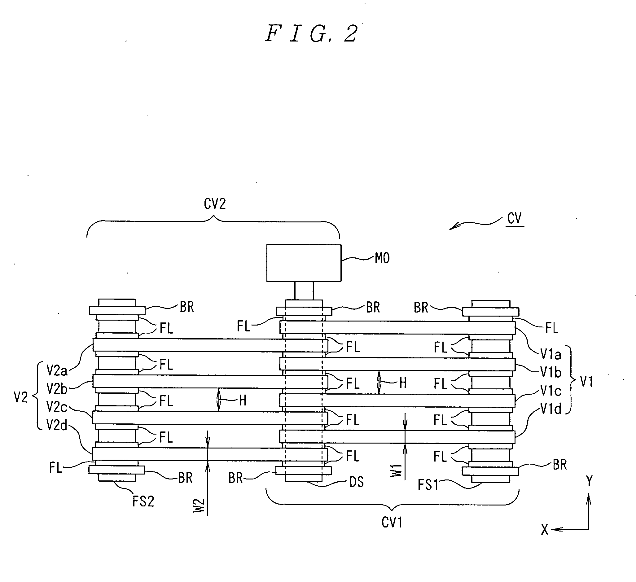
[0034] That is, as a result of comparing a conveying belt having a long peripheral length with conveying belts of the first and second conveying portions by applying the same tension to them, the elongations of the first and second conveying portions respectively having a short peripheral length become smaller. Therefore, it is possible to decrease the elongation of a conveying belt which is produced due to rotation of a driving shaft and decrease the fluctuation of the conveying speed of a printing medium due to the expansion and contraction of a conveying belt and a shift of the landing position of an ink drip to the printing medium due to the vibration of the conveying belt.
[0105] According to the forty-first invention, the discharge performance recovery section does not interrupt conveying of a printing medium because it shelters to the sheltering position while data is printed in a printing medium but the section makes it possible to recover the discharge performance of a printing head by slightly rising when data is not printed in the printing medium.

Problems solved by technology

Moreover, in the case of the printing head of an ink-jet-type printer not applied only to the line type, the solvent of ink is evaporated from a nozzle from which ink drips are discharged which results in the rising of the viscosity of the ink in the nozzle.
In the worst case, the ink is solidified or foreign matter enters the nozzle and the nozzle is clogged, and the performance for discharging ink drips from the nozzle may be deteriorated.
Moreover, in the case of the printing head of an ink jet printer not applied only to the line type, the solvent of ink is evaporated from a nozzle for discharging ink drips and the ink in the nozzle is solidified foreign matter gets into the nozzle to clog it, thereby, the performance for discharging ink drips may be deteriorated.
Moreover, in the case of the printing head of an ink jet printer, the solvent of ink is evaporated from the nozzle for discharging ink drips and the ink in the nozzle is solidified or foreign matter enters the nozzle and thus the nozzle is clogged and thereby, the performance for discharging ink drips from the nozzle may be deteriorated.
However, in the case of the configuration disclosed in JP10-202922A, the conveying speed of a printing medium is fluctuated due to the telescopic motion of a conveying belt or the interval between a printing head and the printing medium becomes unstable because the conveying belt vibrates between conveying rollers and thereby, the landing position of ink drips on the printing medium maybe shifted from a predetermined position.
That is, there is an unsolved problem that it is difficult to lengthen the conveying interval by a conveying belt while maintaining a preferable printing quality.
Therefore, when applying non-marginal printing to an A4-size printing sheet, ink outgoing from the printing area of the printing sheet contaminates a conveying belt.
Moreover, there is an unsolved problem that it is difficult to apply non-marginal printing to a printing sheet having a size smaller than size A4 or a different shape.
That is, the tensile stress and strain are ununiformly generated on the entire perimeter of the conveying belt because of the holes which are formed upon.
This is not preferable for an ink jet printer for printing data in a printing medium by conveying the printing medium through a conveying belt in the point that it is difficult to improve the printing quality.
That is, in the case of conveying by the conveying belt, the conveying speed of the printing medium is fluctuated due to the telescopic motion of the conveying belt or due to the conveying belt vibrates between conveying rollers and thereby, the interval between a printing head and the printing medium becomes unstable and the landing position of ink drips on the printing medium is shifted from a predetermined position.
That is, in the case of the prior art disclosed in the above JP2001-113690A, by forming holes on a conveying belt, there are unsolved problems that fluctuation of the conveying speed and vibration of the conveying belt are encouraged which makes it difficult to improve the printing quality.
Therefore, it is difficult to decrease the time until a protective cap is set to a printing head and the time until the protective cap is removed from the printing head and evacuated.
Therefore, there are unsolved problems that it is difficult to maintain a high reliability of a mechanism portion and to decrease the number of components.
Moreover, in the case of the prior art disclosed in the above JP2002-103638A, it is limited to increase the rotational speed without damaging a line head, thus it is difficult to decrease the time required for recovering the discharge performance, and a mechanism and control for rotation become complex.
Furthermore, because a discharge performance recovery apparatus must be set in a non-printing area, there are unsolved problems that downsizing is difficult and the like.
However, a sufficient effect cannot be obtained for a warp produced as ink infiltrates into a printing medium which has a low rigidity such as a printing sheet.
That is, though the warp of the printing sheet P is temporarily corrected at the spur portion, the warp is produced again after passing through the spur portion and an unsolved problem remains that it is difficult to properly keep the interval between the printing head and the printing sheep P.

Method used


Image

  • Ink jet printer
  • Ink jet printer
  • Ink jet printer

Examples


first embodiment

[0158] the present invention is described below by referring to the accompanying drawings.

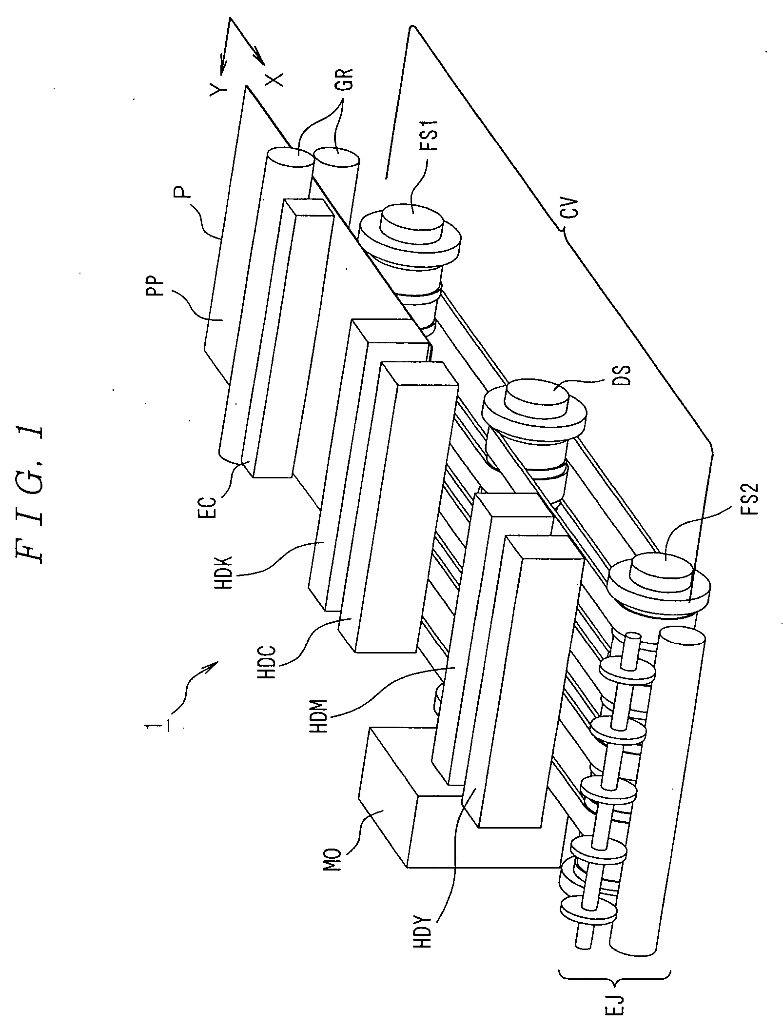
[0159] As shown in FIG. 1, the ink jet printer 1 of the first embodiment has a gate roller GR, an static electricity supply portion EC, sheet conveying portion CV, yellow, magenta, cyan, and black printing heads HDY, HDM, HDC, and HDK for discharging various colors of ink drips of yellow, magenta, cyan, and black, and sheet ejecting portion EJ.

[0160] Details of the above configurations are described below.

[0161] As shown in FIG. 2 which is a top view, the sheet conveying portion CV has a driving shaft DS to which motive power is transferred from a conveying-portion driving motor M0, first and second driven shafts FS1 and FS2 parallel with the driving shaft DS and located at mutually opposite sides at both sides of the driving shaft DS, a first conveying belt V1 applied to the driving shaft DS and the first driven shaft FS1, a second conveying belt V2 applied to the driving shaft DS and the se...

second embodiment

[0218] the present invention is described below by referring to the accompanying drawings.

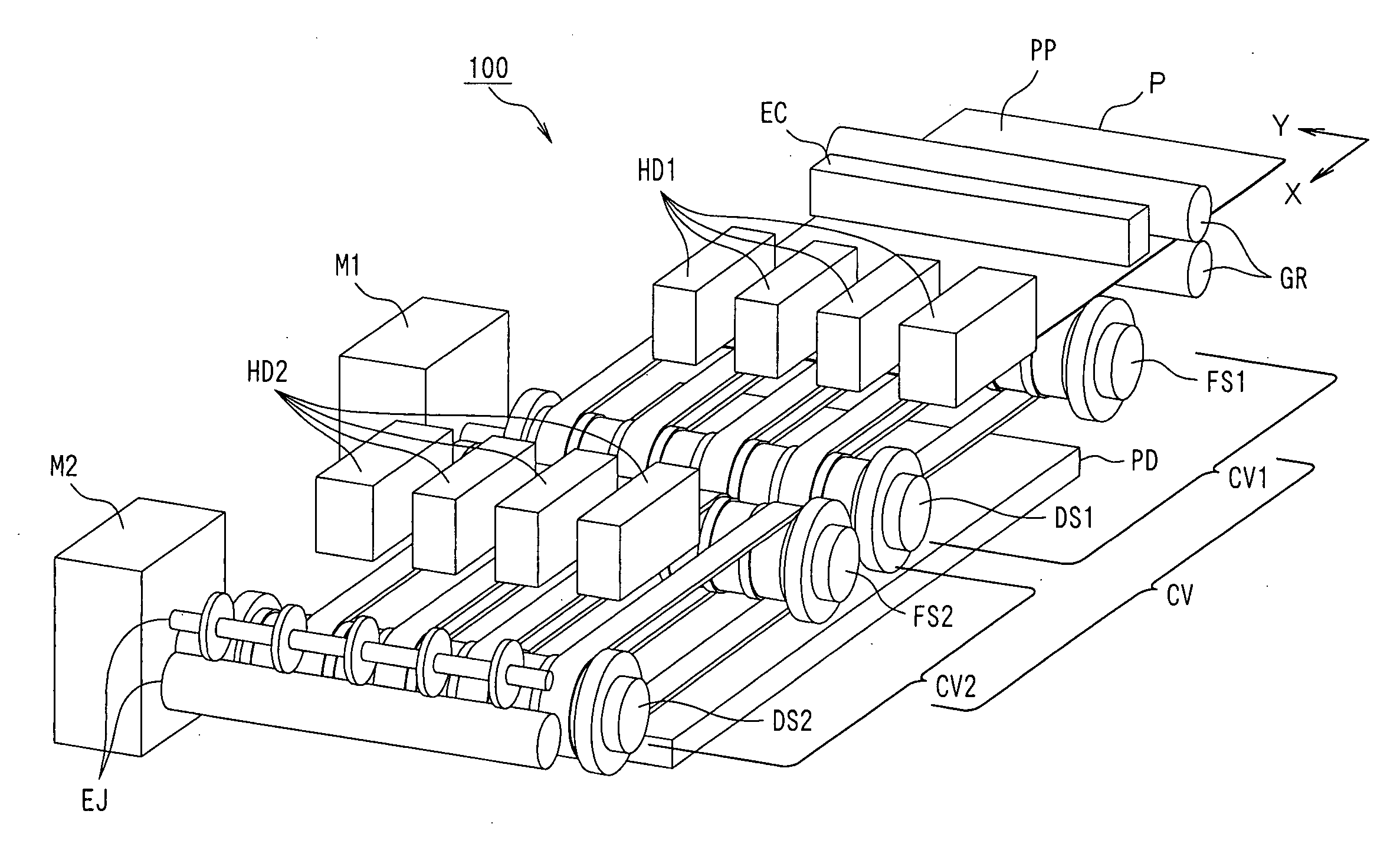
[0219] As shown in FIG. 11, the ink jet printer 100 of the second embodiment has the same configuration as the first embodiment except that a sheet conveying portion CV is constituted by including a first conveying portion CV1, and a second conveying portion CV2 to be driven independently from the first conveying portion CV1, a printing head is constituted of a first printing head group HD1 set on the first conveying portion CV1 and a second printing head group HD2 set on the second conveying portion CV2, and an ink absorbing portion PD is set under the sheet conveying portion CV.

[0220] Therefore, a portion corresponding to that of the first embodiment is provided with the same symbol and its description is omitted.

[0221] As shown in FIG. 12 which is a top view, for the sheet conveying portion CV, the second conveying portion CV2 has a second driving shaft DS2 and a second conveying portion d...

third embodiment

[0284] the present invention is described in accordance with the accompanying drawings.

[0285] In the case of the ink jet printer 1000 of the third embodiment, widths of the printing heads HD3a and HD3b of the ink jet printer 110 shown in FIG. 22 of the second embodiment in Y direction are set equally to those of the printing heads HD1a to HD1c and HD2a to HD2c and the ink absorbing portion PD is omitted. As shown in FIG. 24, the ink jet printer 1000 has the same configuration of the ink jet printer 110 except that the printer 1000 has first and second discharge performance recovery caps CA1 and CA2.

[0286] Therefore, a portion corresponding to that of the ink jet printer 110 is provided with the same symbol and its description is omitted.

[0287] As shown in FIG. 25, the first and second printing head groups HD1 and HD2 are respectively constituted of the printing heads HD1a to HD1d and HD2a to HD2d on the first and second conveying portions CV1 and CV2. Moreover, the printing heads ...


PUM


Abstract

To provide an ink jet printer for discharging ink drips to a printing medium mounted on a conveying belt and conveyed from a plurality of nozzles, in which the printing quality is improved and the printing speed is raised. A printing medium conveying section has a first and second conveying portions connected in the conveying direction of the printing medium and arranging a plurality of conveying belts by mutually keeping a predetermined interval, in which the conveying belts of the first and second conveying portions are set so that an other-hand conveying belt is located between one-hand conveying belts, and a printing head is constituted of a first head set to a position facing the gap between the conveying belts of the first conveying portion and a second head set to a position facing the gap between the conveying belts of the second conveying portion.

Description

BACKGROUND OF THE INVENTION [0001] 1. Field of the Invention [0002] The present invention relates to an ink jet printer for completing printing of data in a printing medium by moving the printing medium without moving a printing head. [0003] 2. Description of the Related Art [0004] In recent years, an ink jet printer (hereafter referred to as line-head-type ink jet printer) is practically used which has a line-type printing head (hereafter referred to as line head) in which many nozzles are arranged over the width or more of a printing medium from a request for increase in the printing speed of an ink jet printer for discharging ink from a nozzle so as to print data in a printing medium. [0005] In the case of this line-head-type ink jet printer, the face of a printing medium on which data will be printed is continuously or intermittently conveyed by facing a face on which the nozzle of a line head is formed. Moreover, the line head selectively discharges ink in accordance with the i...

Claims


Application Information

Patent Timeline
IPC IPC(8): B41J2/01B41J11/00B65H5/02
CPCB41J11/0025B41J11/007B41J11/0065
Inventor YODA, KANEO
Owner SEIKO EPSON CORP
Learn More