Apparatus and method for producing solid fuel using low-grade coal as raw material

Active Publication Date: 2005-09-22
KOBE STEEL LTD
View PDF17 Cites 10 Cited by
  • Summary
  • Abstract
  • Description
  • Claims
  • Application Information

AI Technical Summary

Benefits of technology

[0022] When stirring and slurry circulation are stopped by a power failure or the like to cause blocking due to coal deposits, the apparatus for producing solid fuel according to the present invention is capable of removing the blocking by washing a portion where the coal deposits, without disassembling the apparatus and the need for cooling the slurry. When stirring and slurry circulation are stopped by a power breakdown or the like to cause blocking due to coal deposits, the method for producing solid fuel according to the present invention is capable of removing the blocking by washing a portion where the coal deposits, without disassembling the apparatus and the need for cooling the slurry.

Problems solved by technology

Namely, the porous coal (low-grade coal) contains a large quantity of water, and thus transport of the porous coal equals to transport of water, thereby increasing transport cost.
Therefore, the transport quality is degraded, and the calorie is decreased due to the high water content.
However, the dehydration by a usual drying method has the danger that a spontaneous combustion accident occurs due to oxygen adsorption and oxidation reaction at active sites present in the pores of the dehydrated porous coal.
The slurry state is maintained by stirring and circulating the slurry, but when the stirring and circulation of the slurry are stopped by a power failure, an apparatus failure, or the like, the solid (coal) contained in the slurry settles to cause blocking due to coal deposits at the bottom of the mixing tank, a portion (for example, a portion between the bottom of the mixing tank and the slurry pump) of the slurry circulating passage of the mixing tank, the bottom of the evaporator, a portion (for example, a portion between the evaporator and the slurry pump) of the slurry circulating passage of the evaporator, and the like.
In this blocking, the apparatus cannot be restarted.
In this case, the slurry in the evaporator contains moisture at high temperature and high pressure, and thus the slurry flushes when the vessel (evaporator) is opened, thereby causing an accident.
However, the cooling requires several days because the evaporator is covered with a heat insulator, and thus the operation must be stopped for a long period of time, thereby requiring a long time for restarting the operation.

Method used


Image

  • Apparatus and method for producing solid fuel using low-grade coal as raw material
  • Apparatus and method for producing solid fuel using low-grade coal as raw material
  • Apparatus and method for producing solid fuel using low-grade coal as raw material

Examples


first embodiment

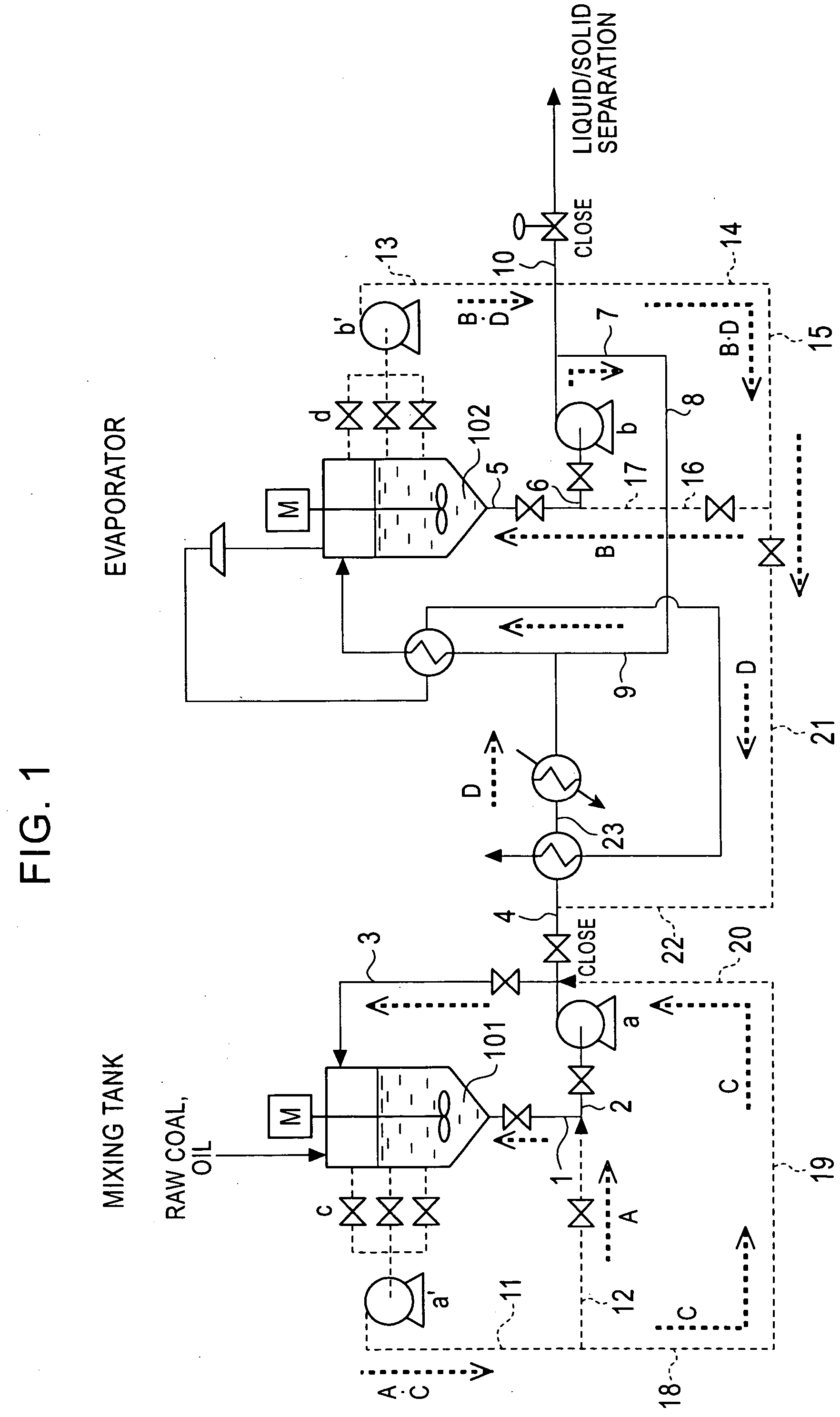
[0029] As described above, the apparatus comprises the passage (referred to as “passage A” hereinafter) for introducing the supernatant, which occurs due to settling of the solid in the slurry in the mixing tank, to a portion between the bottom of the mixing tank and the first slurry pump of the first slurry circulating passage through the third pump, and the passage (referred to as “passage B” hereinafter) for introducing the supernatant, which occurs due to settling of the solid in the slurry in the evaporator, to a portion between the bottom of the evaporator and the second slurry pump of the second slurry circulating passage through the fourth pump. For example, in an apparatus shown in FIG. 1 (first embodiment of the present invention), the passage A is denoted by reference character A (including a passage 11 (having a third pump a′) and a passage 12), and the passage B is denoted by reference character B (including a passage 13 (having a fourth pump b′) to a passage 17).

[0030]...

second embodiment

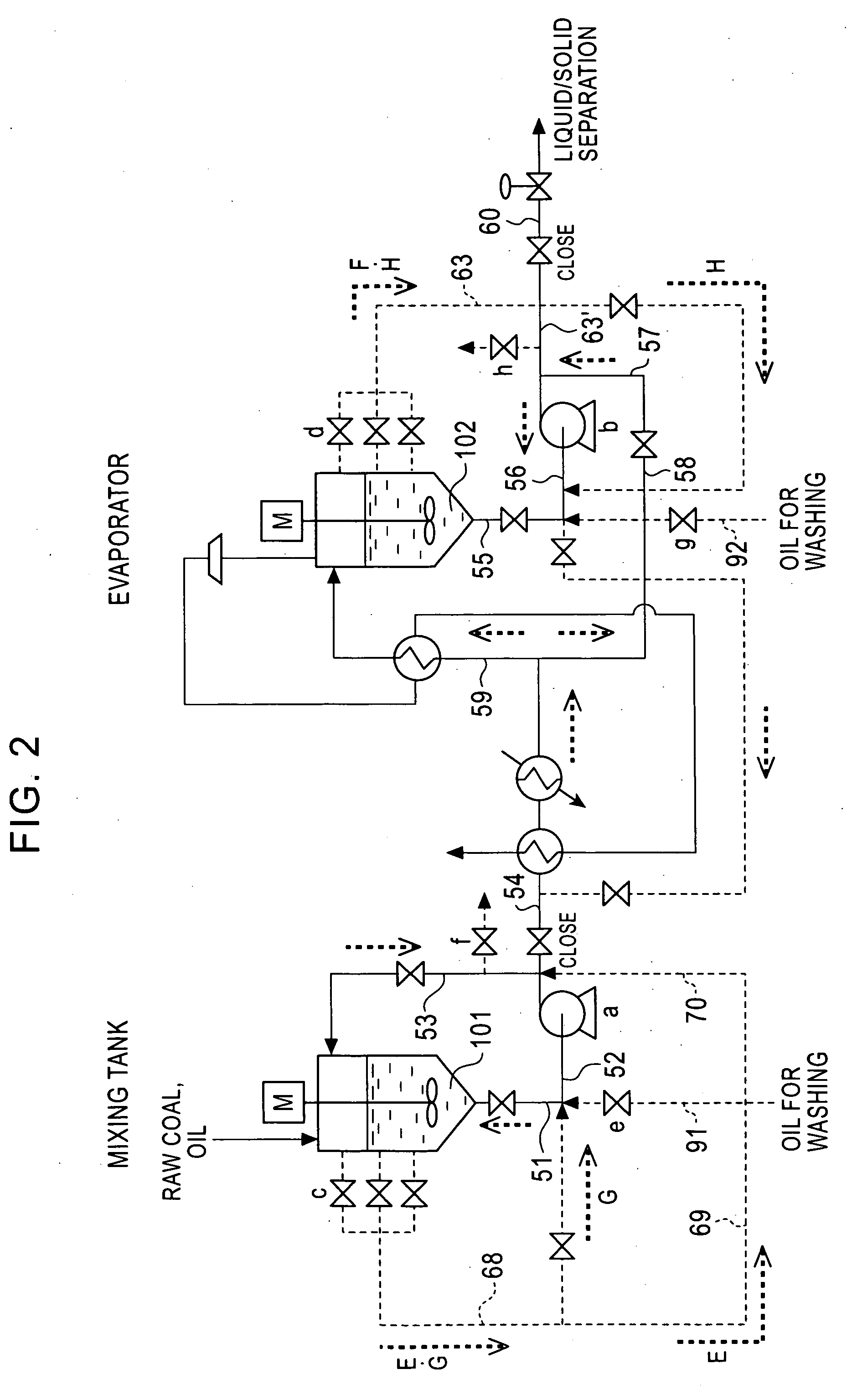
[0039] As described above, the apparatus for producing solid fuel according to the present invention comprises the mixing tank for mixing the oil mixture containing heavy oil and solvent oil with the low-grade coal to prepare the raw material slurry, the first slurry circulating passage for introducing the raw material slurry to the top of the mixing tank from the bottom thereof through the first slurry pump, the evaporator for removing water vapor by heating the raw material slurry introduced from the raw material slurry supply passage branching from the first slurry circulating passage, the second slurry circulating passage for introducing the slurry to the top of the evaporator from the bottom thereof through the second slurry pump, and the liquid / solid separator for liquid / solid separation of the slurry introduced from the slurry supply passage, which branches from the second slurry circulating passage. The apparatus for producing solid fuel further comprises a passage for intro...


PUM


Abstract

An apparatus for producing solid fuel includes a passage for introducing a supernatant in a mixing tank into a portion between the bottom of the mixing tank and a first slurry pump of a first slurry circulating passage using a third pump, and a passage for introducing a supernatant in an evaporator into a portion between the bottom of the evaporator and a second slurry pump of a second slurry circulating passage using a fourth pump. A method for producing a solid fuel includes introducing a supernatant in a mixing tank into a first slurry circulating passage, for washing a portion where coal deposits, and introducing a supernatant in an evaporator into a second slurry circulating passage, for washing a portion where coal deposits.

Description

BACKGROUND OF THE INVENTION [0001] 1. Field of the Invention [0002] The present invention belongs to a technical field relating to an apparatus and method for producing solid fuel using low-grade coal as a raw material. [0003] 2. Description of the Related Art [0004] With respect to a technique for producing solid fuel using low-grade coal as a raw material, a known method for producing solid fuel is that disclosed in Japanese Unexamined Patent Application Publication No. 7-233383. The method for producing solid fuel disclosed in this document comprises mixing an oil mixture containing heavy oil and solvent oil with porous coal to prepare a raw material slurry, heating the slurry to progress dehydration and fill the pores of the porous coal with the oil mixture containing the heat oil and the solvent oil, and then subjecting the slurry to liquid / solid separation. The porous carbon corresponds to low-grade coal. [0005] The method for producing solid fuel disclosed in the above docume...

Claims


Application Information

Patent Timeline
IPC IPC(8): C10L5/00C10L5/04C10L9/08C10L9/10
CPCC10L5/04C10L5/366C10L5/361
Inventor SUGITA, SATORUDEGUCHI, TETSUYASHIGEHISA, TAKUOKATSUSHIMA, SHINICHI
Owner KOBE STEEL LTD
Why Eureka
Try Eureka