
Method and system for superheterodyne detection of an optical input signal

a detection system and optical input technology, applied in the field of optical measurement and measuring systems, can solve the problems of reducing the ability to measure spectral features between dwdm channels, amplitude accuracy of heterodyne optical spectrum analyzers degraded by phase noise, and the bandwidth limitation of heterodyne beat signals from photodetectors b>112/b> normally to provide high spectral resolution, etc., to achieve the effect of reducing

Inactive Publication Date: 2005-09-15
AGILENT TECH INC
View PDF10 Cites 19 Cited by
  • Summary
  • Abstract
  • Description
  • Claims
  • Application Information

AI Technical Summary

Benefits of technology

The invention is a system and method for detecting optical signals using a special technique called superheterodyne detection. This system converts the optical signal into an electrical signal through two heterodyne conversions, which reduces the effect of intensity noise and allows for easier processing. The system can separate the image signals more effectively, resulting in higher resolution and accuracy when measuring optical characteristics. Additionally, the system can further filter the image signals using a band pass filter, allowing for even better resolution and amplitude accuracy. Overall, this invention provides a more efficient and accurate way to detect optical signals.

Problems solved by technology

For closely spaced dense wavelength-division-multiplexed (DWDM) systems, the limited resolution of conventional diffraction grating-based and autocorrelation-based optical spectrum analyzers (OSA) reduces the ability to measure spectral features between DWDM channels.
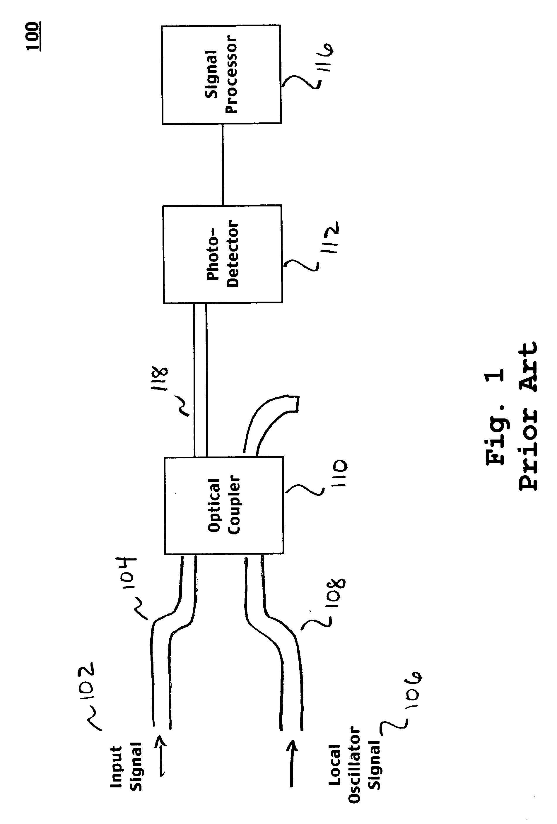
However, in system 100, the resulting heterodyne beat signal from the photodetector 112 is normally bandwidth limited to provide high spectral resolution.
In consequence, amplitude accuracy of the heterodyne optical spectrum analyzer is degraded by the phase noise.
Moreover, intensity noise is a problem affecting prior art heterodyne optical spectrum analyzers.
In some instances, the intensity noise renders measurement results inaccurate or unusable.
As a consequence, amplitude accuracy of the heterodyne optical spectrum analyzer is degraded by the intensity noise.

Method used


Image

  • Method and system for superheterodyne detection of an optical input signal
  • Method and system for superheterodyne detection of an optical input signal
  • Method and system for superheterodyne detection of an optical input signal

Examples


Embodiment Construction

[0022] In the following detailed description of embodiments in accordance with the invention, numerous specific details are set forth in order to provide a thorough understanding of embodiments in accordance with the invention. However, it will be recognized that embodiments in accordance with the invention may be practiced without these specific details. In other instances, well known methods, procedures, components, and circuits have not been described in detail as not to unnecessarily obscure aspects of embodiments in accordance with the invention.

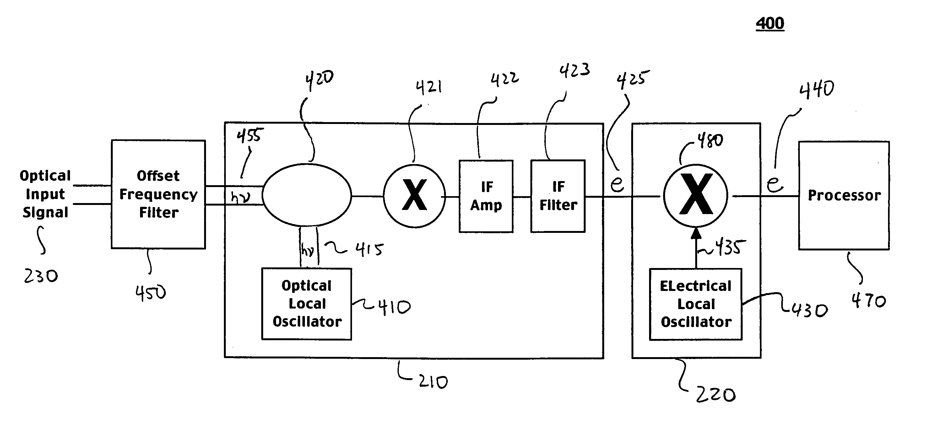
[0023] Accordingly, embodiments in accordance with the invention provide a superheterodyne optical analyzer performing double conversion. That is, embodiments in accordance with the invention provide superheterodyne optical analyzers that are capable of wider frequency or wavelength separation (e.g., several hundreds of picometers) between created image signals than in detection schemes of the prior art. This is achieved by operating a...


PUM

PropertyMeasurementUnit
frequencyaaaaaaaaaa
frequenciesaaaaaaaaaa
distanceaaaaaaaaaa

Abstract

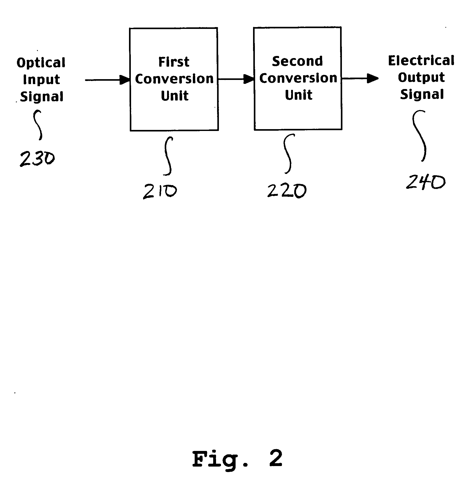
A system and method for superheterodyne detection in accordance with the invention. The system comprises a first conversion unit for performing a first heterodyne operation on an optical input signal to generate an electrical IF signal. A second conversion unit is electrically or optically coupled to the first conversion unit. The second conversion unit performs a second heterodyne operation to generate an electrical output signal suitable for signal processing.

Description

TECHNICAL FIELD [0001] The various embodiments in accordance with the invention relate generally to the field of optical measurements and measuring systems. Specifically, various embodiments in accordance with the invention relate to a system and method for superheterodyne detection of an optical input signal. BACKGROUND ART [0002] Increasing bandwidth demands on fiber-optic networks have driven network designs toward more closely spaced optical wavelength channels and also toward higher transmission bit rates. Spectral characteristics of these lightwave systems are indicators of transmission performance. For closely spaced dense wavelength-division-multiplexed (DWDM) systems, the limited resolution of conventional diffraction grating-based and autocorrelation-based optical spectrum analyzers (OSA) reduces the ability to measure spectral features between DWDM channels. [0003] As an alternative to conventional OSAs, optical heterodyne detection systems can be utilized to monitor DWDM...

Claims


Application Information

Patent Timeline
Patent Type & Authority Applications(United States)
IPC IPC(8): G02F1/35H04B10/02H04B10/04H04B10/06H04B10/142H04B10/148H04B10/152H04B10/18H04J14/00H04J14/02
CPCH04B10/64H04B10/60
Inventor BANEY, DOUGLAS M.TAN, TUN S.SZAFRANIEC, BOGDAN
Owner AGILENT TECH INC
Learn More