Transmission type diffraction grating

a diffraction grating and transceiver technology, applied in the field of transceiver, can solve the problems of limited spectral range, less diffraction efficiency, range limitations, etc., and achieve the effects of low polarization dependent loss, high diffraction efficiency, and high resolving power and dispersion

Inactive Publication Date: 2005-09-15
NIPPON SHEET GLASS CO LTD
View PDF6 Cites 13 Cited by
  • Summary
  • Abstract
  • Description
  • Claims
  • Application Information

AI Technical Summary

Benefits of technology

[0014] The object of the present invention is to overcome these problems and to provide a transmission grating that can provide high diffraction efficiency and low polarization dependent loss over a wide wavelength range even when the groove pitch is small and resolving power and dispersion are high.

Problems solved by technology

However, the use of diffracted light with a higher order of diffraction generally results in less diffraction efficiency compared to diffracted light with lower orders.
Furthermore, when a high-order diffracted light is used, range limitations result from the free spectral range.
This range restriction is a significant problem for use of diffraction gratings with multiple wavelengths or wide wavelength ranges.
This range restriction can be avoided by using filters or multiple detectors or the like (e.g., see Non-patent Document 1), but these measures led to problems such as light energy loss and increased complexity in structure.
However, it is known that increasing resolving power and dispersion by increasing the number of grooves and decreasing the groove pitch can lead to a tendency to make diffraction efficiency dependent on polarization or reduce energy efficiency.
Also, reliably obtaining high diffraction efficiency at over wide wavelength ranges becomes more difficult.

Method used


Image

  • Transmission type diffraction grating
  • Transmission type diffraction grating
  • Transmission type diffraction grating

Examples


first embodiment

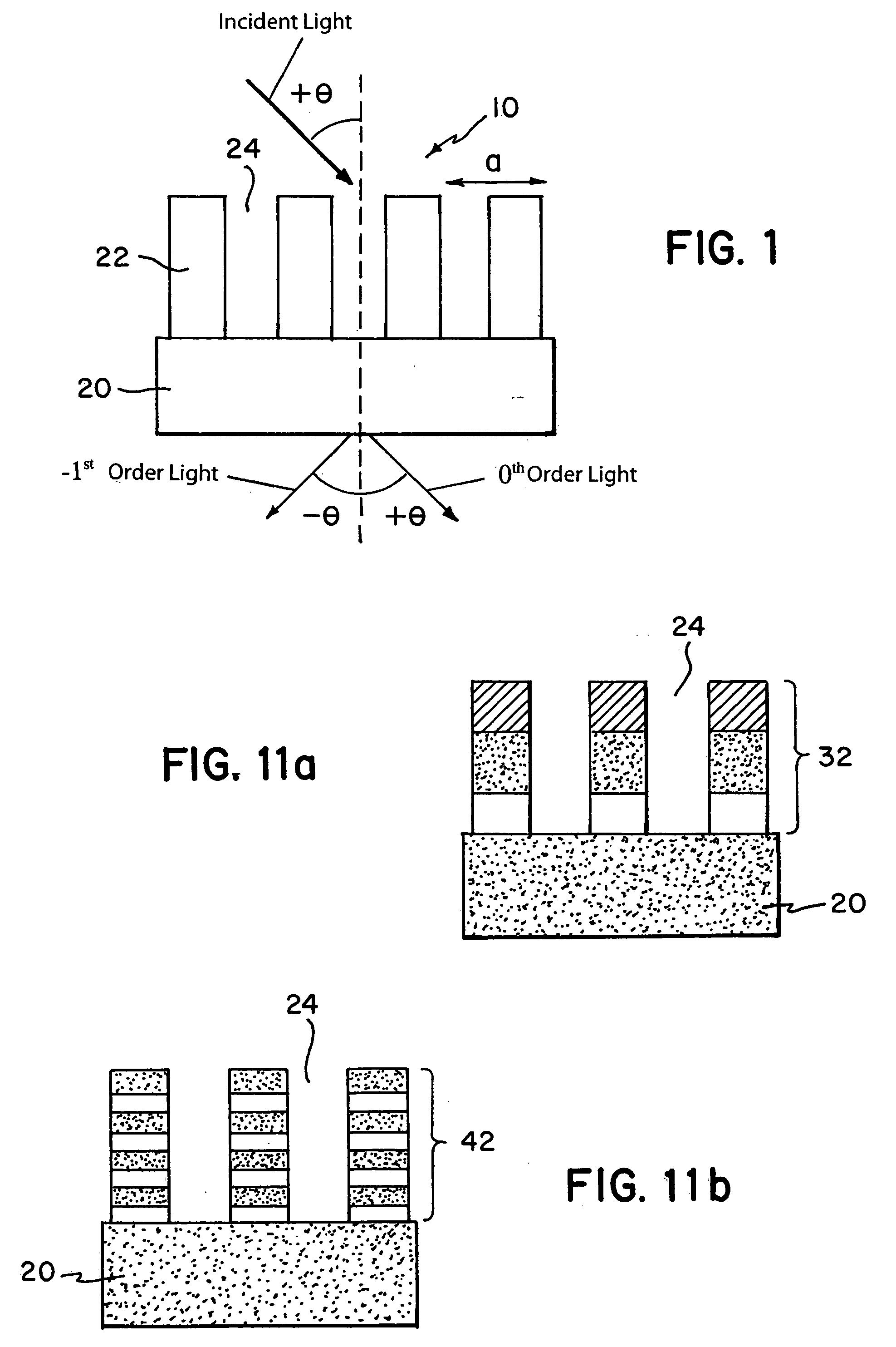
[0057] Using the method described above, a transmission grating was formed from a quartz substrate (1.45 index of refraction at 1500 nm wavelength) with 939 grooves per mm, a proportion of groove width d relative to groove pitch a (duty cycle D=d / a) of 0.8, and rectangular grooves of 5.3 micron depth.

[0058] A center wavelength of λc=1500 nm was used for this diffraction grating, and light was applied at an incidence angle of 45 deg from the side with the diffraction grating. The diffraction efficiency was measured in a system where the 1500 nm light had a −1 order diffraction angle of −45 deg.

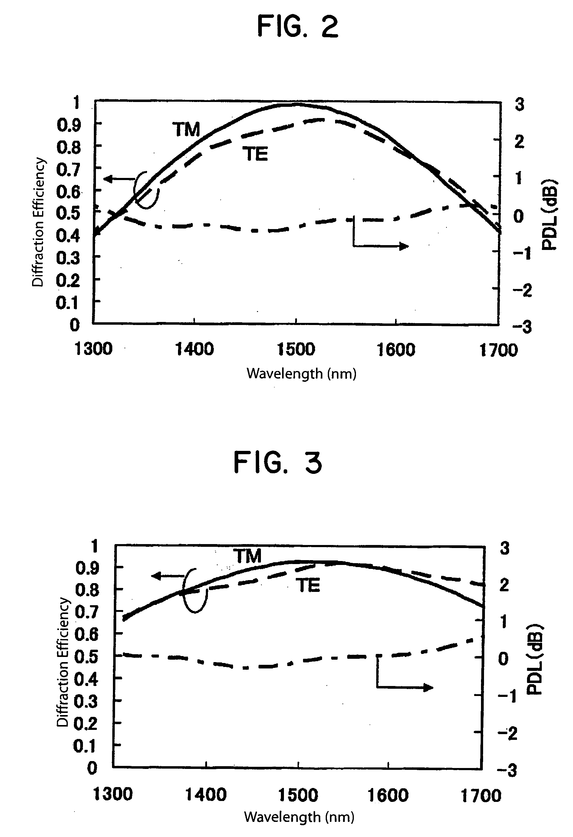
[0059]FIG. 2 shows diffraction efficiency and polarization dependent loss (PDL) as a factor of wavelength for TM mode and TE mode. Good characteristics were obtained, with TE mode and TM mode both resulting in at least 80% in the 1500+ / −100 nm range, and a PDL of no more than + / −1 dB within the 1500+ / −300 nm range.

second embodiment

[0060] Using a method similar to that of the first embodiment, a transmission grating was formed from a quartz substrate with 800 grooves per mm, a duty cycle of 0.7, and rectangular grooves of 3.9 micron depth. A center wavelength of λc=1550 nm was used for this diffraction grating, and light was applied at an incidence angle of 38 deg from the side with the diffraction grating. The diffraction efficiency was measured in a system where the 1550 nm light had a −1 order diffraction angle of −38 deg. Good characteristics were obtained, as shown in FIG. 3, with the diffraction efficiency for both TE mode and TM mode being at least 80% in the 1550+ / −140 nm range, and the PDL being no more than + / −1 dB in the 1550+ / −250 nm range.

third embodiment

[0061] A TiO2 film was formed to a thickness of 1.4 micron on a quartz substrate. This TiO2 film was processed to form a transmission grating with rectangular grooves, 900 grooves per mm, and a duty cycle of 0.5. The grooves were etched to remove all of the TiO2 film, thus resulting in a groove depth of 1.4 micron identical to the thickness of the TiO2 film.

[0062] A center wavelength of λc=1550 nm was used for this diffraction grating, and light was applied at an incidence angle of 44 deg from the side with the diffraction grating. The diffraction efficiency was measured in a system where the 1550 nm light had a −1 order diffraction angle of −44 deg. Good characteristics were obtained, as shown in FIG. 4, with the diffraction efficiency for TE mode in a range of approximately 1500-1700 nm and TM mode in a range of approximately 1600-1800 nm being at least 80%, and the PDL being no more than + / −1 dB in the 1550+ / −250 nm range.


PUM


Abstract

A transmission grating that provides low polarization dependent loss over a wide wave range and provides high diffraction efficiency even with a small groove pitch and high resolving power and dispersion. In a transmission grating 10, multiple parallel ridges 22 that are transparent for the wave range to be used are disposed on one side of a substrate 20 that is transparent for the wave range to be used. Parallel grooves 24 are formed at a fixed pitch a between these ridges. Light is applied from the surface of the transmission grating on which the grooves are formed and diffracted light is extracted from the substrate surface on which grooves are not formed. The groove pitch a is set to a range of 0.51 λc-1.48 λc, where λc is the central wavelength.

Description

INCORPORATION BY REFERENCE [0001] The present application claims priority under 35 U.S.C. §119 to Japanese Patent Application No. 2004-069269 filed on Mar. 11, 2004. The content of the application is incorporated herein by reference in its entirety. FIELD OF THE INVENTION [0002] The present invention relates to a transmission grating used in spectrum analysis, optical measurement, optical communication, and the like. BACKGROUND OF THE INVENTION [0003] In a diffraction grating with a groove count N per unit width and a width W, a resolving power λ / Δλ of this diffraction grating can be expressed as follows, where the m-th order diffraction of a light with a wavelength λ has an angle of diffraction of θ′: [0004]λ / Δλ=mNW [0005] Also, the angular dispersion Δθ′ / Δλ is expressed as follows. [0006]Δθ′ / Δλ=mN / cos θ′[0007] Higher resolving power and angular dispersion improves the precision and sensitivity of the analyzer or measurement device. Also, the optical system can be made more compact...

Claims


Application Information

Patent Timeline
Patent Type & Authority Applications(United States)
IPC IPC(8): G01J3/28G02B5/18
CPCG02B5/1871
Inventor HIKICHI, NAOKONAKAMA, KENICHI
Owner NIPPON SHEET GLASS CO LTD
Why Eureka
Try Eureka