
Apparatus and Method for Increasing Efficiency of Electric Motors

a technology of electric motors and apparatuses, applied in the direction of polyphase induction motor starters, windings, dynamo-electric converter control, etc., can solve the problems of inability to achieve power factors in the range of 0.90 and greater at low load conditions, and inability to achieve power factors in the range of 0.90 and greater. , to achieve the effect of improving the power factor of a motor and reducing kilowatt consumption

Inactive Publication Date: 2005-09-15
ADVENTECH LLC
View PDF9 Cites 8 Cited by
  • Summary
  • Abstract
  • Description
  • Claims
  • Application Information

AI Technical Summary

Benefits of technology

[0006] U.S. Pat. No. 4,446,416A to Wanlass, granted May 1, 1984, entitled “Polyphase Electric Machine Having Controlled Magnetic Flux Density” discloses a stator core having main windings and additional control windings. The flux density is optimized in a polyphase machine by controlling the flux density in the stator core. More particularly, a main polyphase stator winding is wound on a magnetic core and includes a plurality of windings where each winding represents a single phase. Capacitors are connected in series to each of the windings. The capacitors reduce reactive power.
[0026] The novel electric motor of this invention includes main windings just like a conventional motor. However, it differs in that an additional winding that performs a de-saturation function is also provided. Each additional winding is electrically connected in series with a capacitor. Each additional winding and capacitor are electrically connected in parallel to the main winding. Significantly, the additional winding is reversely connected relative to its associated main winding so that the direction of current flow through the main winding is opposite to the direction of current flow through the additional winding. Moreover, the current flowing through the main winding is out of phase with the opposed current flowing through the additional winding. The proper size capacitor allows the precise phase shift required for the inventive method to perform.
[0033] The invention also has other aspects that not only improves the power factor of a motor but which also reduces kilowatt consumption.

Problems solved by technology

The Wanlass and the Wen motors, like all motors heretofore known, operate most efficiently at full load and are less efficient in low load conditions.
However, the conventional wisdom has been for many decades that motors will always operate at reduced efficiency when the loads applied thereto are reduced because such lower efficiency at low loads is an inherent feature of motors.
Power factors in the range of 0.90 and greater at low load conditions have been considered to be impossible to attain.
The penalty is even greater if such motors are often used at low duty cycle (from no load to seventy-five percent (75%) load) or if such motors are fed through V.F.D (Variable Frequency Drive).

Method used


Image

  • Apparatus and Method for Increasing Efficiency of Electric Motors
  • Apparatus and Method for Increasing Efficiency of Electric Motors
  • Apparatus and Method for Increasing Efficiency of Electric Motors

Examples


Embodiment Construction

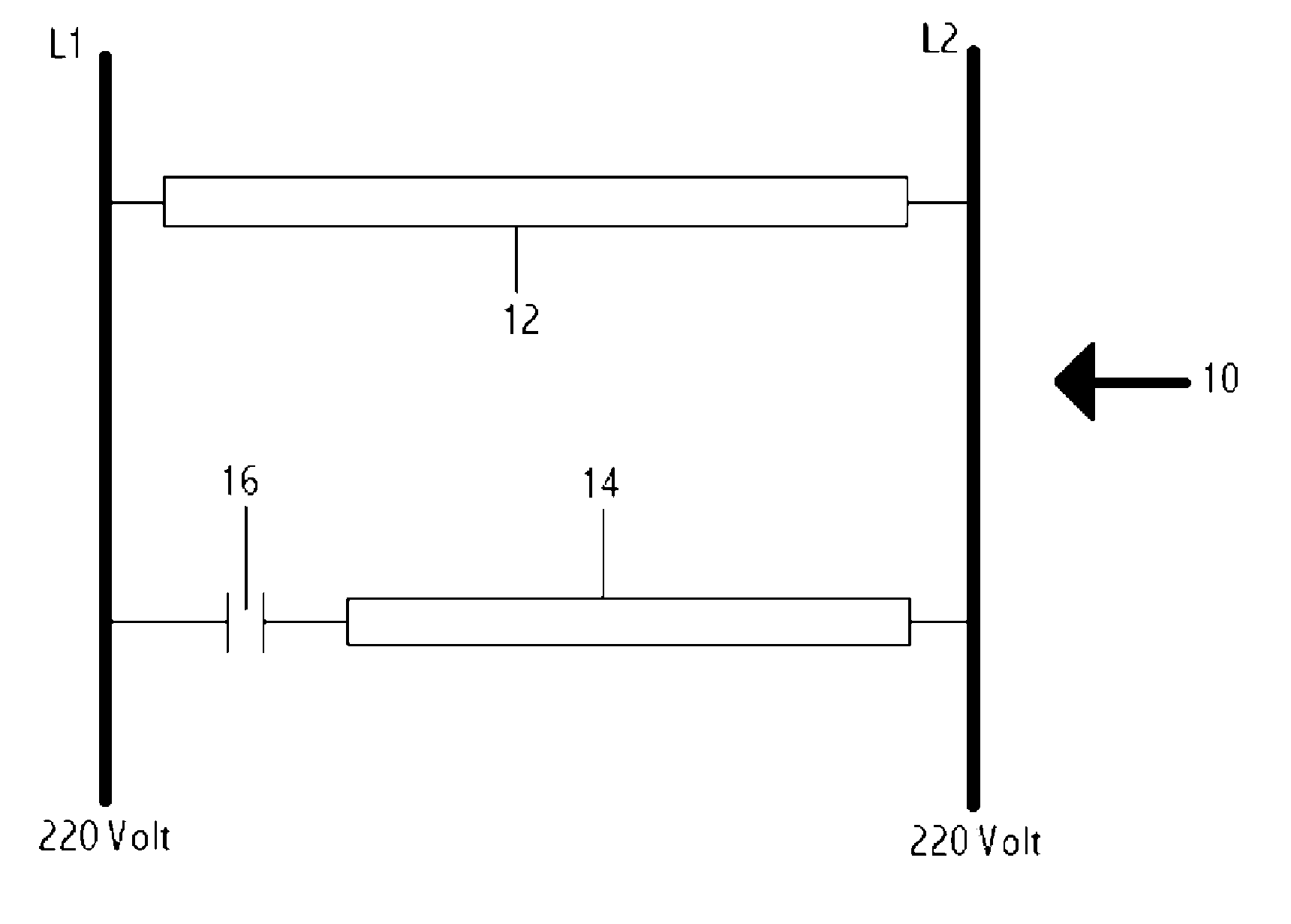
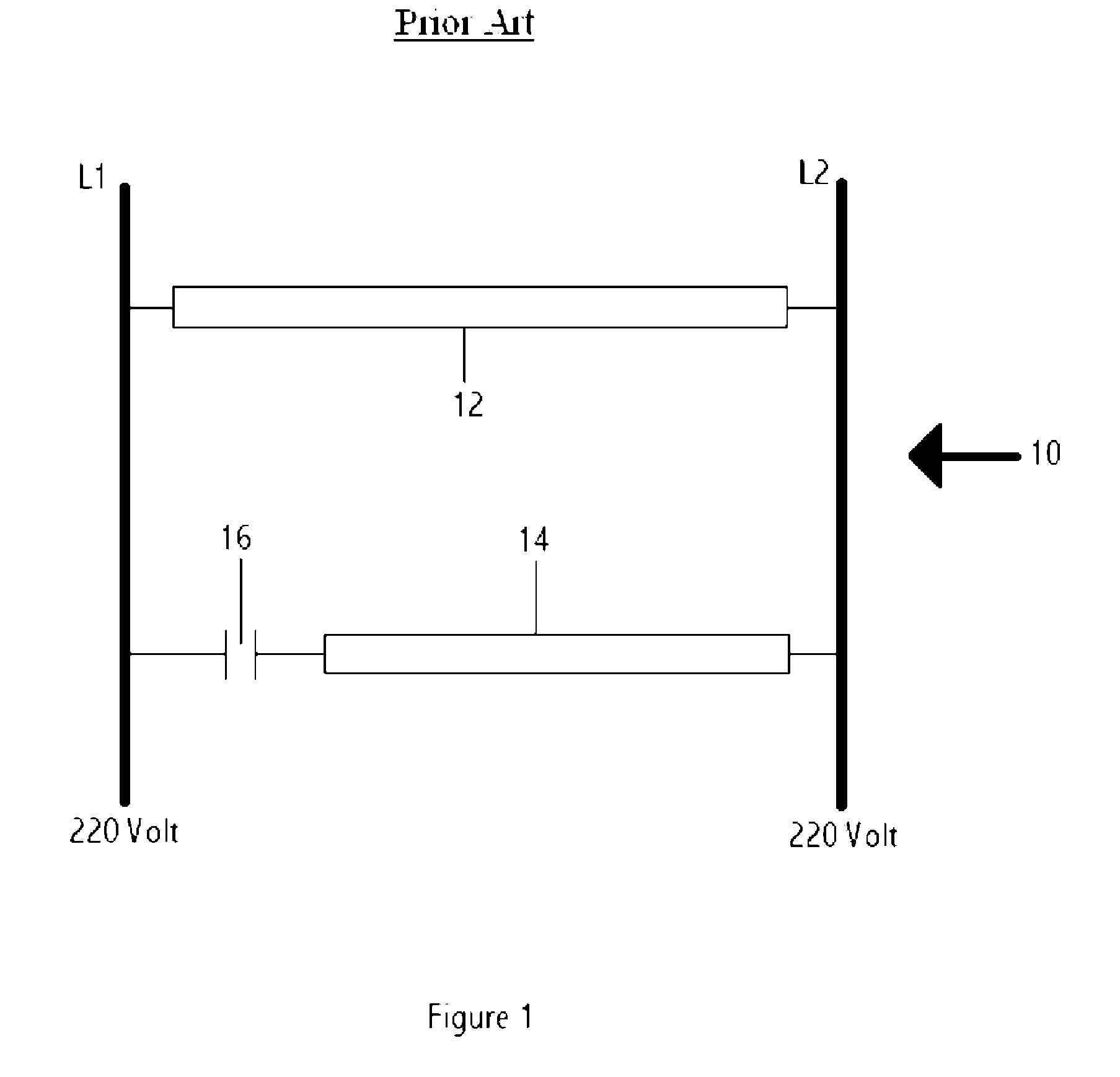
[0050] Referring now to FIG. 1, it will there be seen that a prior art single phase motor is diagrammatically depicted and denoted by the reference numeral 10 as a whole.

[0051] Single phase motor 10 includes a run winding 12, a start winding 14, and a run capacitor 16. Capacitor 16 de-phases the start winding immediately after the start sequence, when running speed is attained. It does not improve the power factor of motor 10. Current flowing through winding 14 flows in relation with winding 12 to determine the rotation direction needed by the motor application.

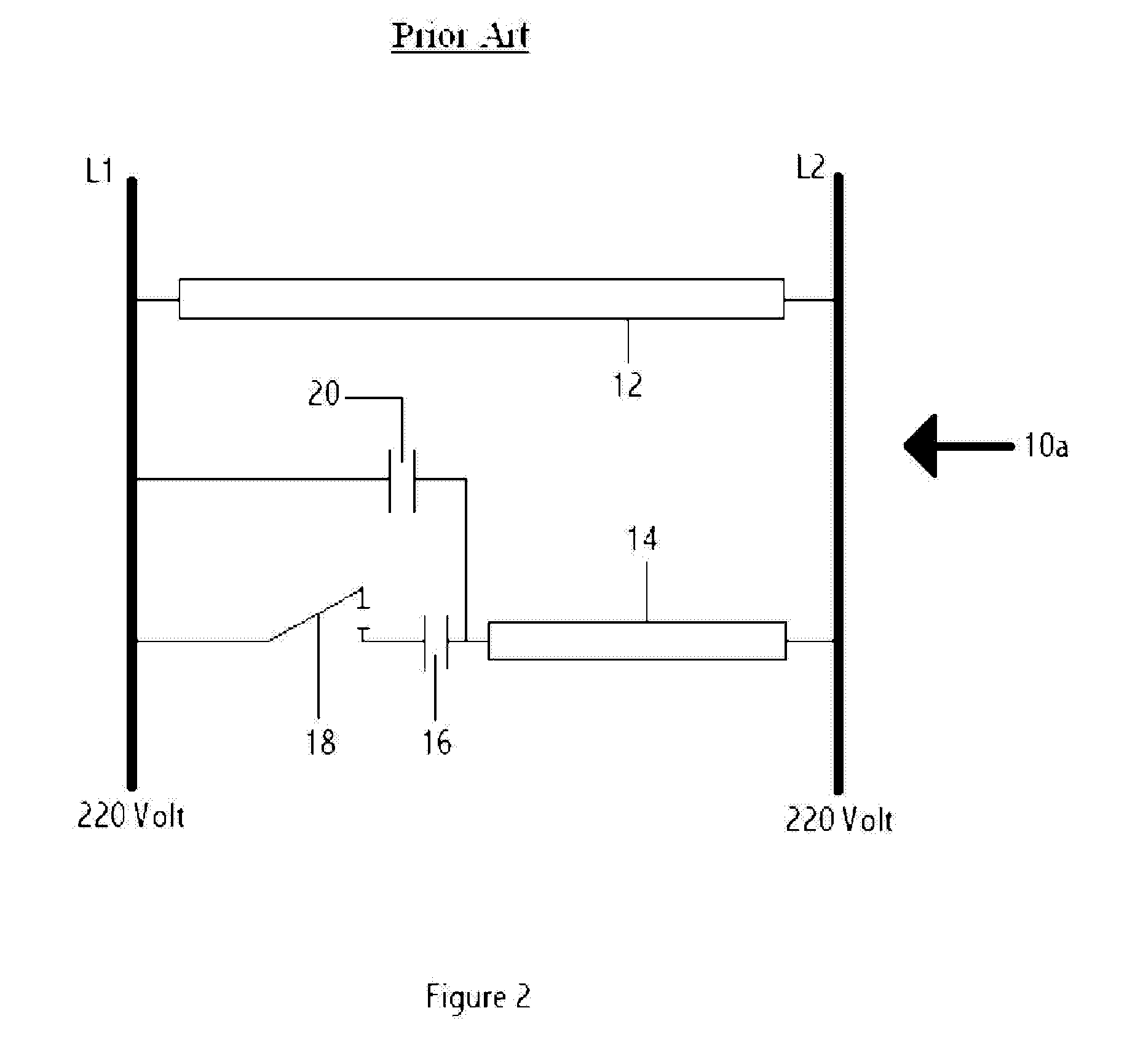
[0052] Single phase electric motors commonly include a start capacitor in series with a centrifugal switch or a disconnecting relay that forms a part of the start winding circuit. An accurate calculation of the run capacitor sizes in microfarads optimizes the efficiency of the electric motor, thereby enhancing starting torque, starting and running current, and temperatures.

[0053] For example, FIG. 2 diagrammatically depict...


PUM


Abstract

A single or multiphase alternating current electric motor or synchronous generator includes main windings and additional windings that perform de-saturation of the magnetic field of the main windings. Each additional winding is fed through at least one capacitor in a different phase angle and opposite field directions from the respective main windings. The total cross sections of the wire used on each main and additional winding are of predetermined sizes and preferably follow the approximate ratio of approximately two-thirds (⅔) for the main winding and approximately one-third (⅓) for the additional winding, and the respective capacitor values are predetermined. The number of turns of each additional winding is from fifty to one hundred percent (50%-100%) of the number of turns of its respective main winding. The two windings are built simultaneously in a single operation.

Description

CROSS-REFERENCE TO RELATED DISCLOSURES [0001] This continuation-in-part disclosure claims the benefit of co-pending U.S. patent application Ser. No.10 / 602,966, filed Jun. 24, 2003 by the same inventor, which disclosure relates to French Patent Application Number 0207820000 filed Jun. 25, 2002, now French patent No. FR 2841404.BACKGROUND OF THE INVENTION [0002] 1. Field of the Invention [0003] This invention relates to electric motors and synchronous generators. More particularly, it relates to a motor or generator that operates at a very high efficiency over a broad range of loads. [0004] 2. Description of the Prior Art [0005] Single phase alternating current electric motors are typically used for low horse power applications. Their range may extend from a fractional horsepower up to about ten horsepower. Three phase motors are typically used when the horsepower requirements exceed ten horsepower. [0006] U.S. Pat. No. 4,446,416A to Wanlass, granted May 1, 1984, entitled “Polyphase E...

Claims


Application Information

Patent Timeline
Patent Type & Authority Applications(United States)
IPC IPC(8): H02K17/08H02K17/12H02P1/44H02P25/04
CPCH02K3/28H02K17/08H02K17/12H02P25/24H02P1/44H02P25/04H02K19/36H02K3/00H02K11/00H02K23/02
Inventor GOCHE, GERALD
Owner ADVENTECH LLC
Learn More