
Rotor for an electric machine

a technology of electric machines and rotors, which is applied in the direction of electric devices, dynamo-electric machines, magnetic circuits, etc., can solve the problems of difficulty in achieving sufficient power density and relatively expensive permanent magnet types, and achieve the effects of reducing magnetic flux leakage, improving the flux density of air gaps between the rotor and the stator, and increasing the resistance of the flux path to the centre section

Active Publication Date: 2021-08-10
JAGUAR LAND ROVER LTD
View PDF18 Cites 1 Cited by
  • Summary
  • Abstract
  • Description
  • Claims
  • Application Information

AI Technical Summary

Benefits of technology

This patent is about a new design for an electric machine that reduces magnetic flux leakage and improves torque characteristics. It includes a support frame with flux barriers that control magnetic flux leakage into the centre section of the support frame. By controlling flux leakage, the flux density in the airgap between the rotor and stator can be improved. The design also includes elongated bridge elements that inhibit magnetic flux leakage, and inner flux barriers that are arranged to reduce flux leakage. These features contribute to the improved performance of the electric machine.

Problems solved by technology

However, these characteristics may rely on the use of high energy dense permanent magnets which reduce the required level of electric loading and the associated winding losses for a given power density.
However, these types of permanent magnets are relatively expensive.
However, there remain challenges in achieving sufficient levels of power density, while mitigating the demagnetization risk under field weakening and short circuit conditions.

Method used


Image

  • Rotor for an electric machine
  • Rotor for an electric machine
  • Rotor for an electric machine

Examples


Embodiment Construction

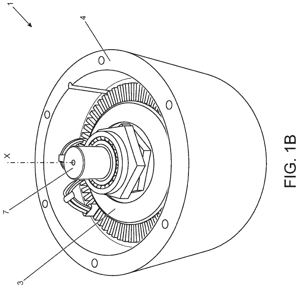
[0042]An electric machine 1 in accordance with an embodiment of the present invention will now be described with reference to the accompanying Figures. The electric machine 1 has particular application as a traction motor in a vehicle 2 (illustrated in FIG. 7).

[0043]The electric machine 1 comprises a rotor 3 and a stator 4. A plan view of the electric machine 1 is shown in FIG. 1A and a perspective view is shown in FIG. 1B. A perspective view of the rotor 3 is shown in FIG. 2; and a perspective view of the stator 4 is shown in FIG. 3. The electric machine 1 has a longitudinal (rotational) axis X (extending perpendicular to the plane of the page in FIG. 1A) about which the rotor 3 rotates. The electric machine 1 described herein has a base operating speed of 3000 rpm and a peak operating speed of 15000 rpm. The stator 4 is of conventional design and has an outer diameter of 205 mm. The rotor 3 has an outer diameter of 140 mm and a stack length of 195 mm. An airgap of 0.5 mm is provid...


PUM


Abstract

The present disclosure relates to a rotor (3) for an electric machine (1). The rotor (3) is composed of a support frame (5) having a centre section (8) and a plurality of spokes (9). The spokes (9) extend outwardly from the centre section (8). The spokes (9) each have at least first and second bridge elements (12A, 12B) formed by one or more flux barrier (13). The first and second bridge elements (12A, 12B) are configured to control magnetic flux leakage into said centre section (8). The present disclosure also relates to an electric machine (1) having a rotor (3) of this type.

Description

RELATED APPLICATIONS[0001]This application is a 35 U.S.C. § 371 national stage application of PCT Application No. PCT / EP2016 / 081078, filed on Dec. 14, 2016, which claims priority, from Great Britain Patent Application No. 1600711.4, filed on Jan. 14, 2016, the contents of which are incorporated herein by reference in their entireties. The above-referenced PCT International Application was published in the English language as International Publication No. WO 2017 / 121567 A1 on Jul. 20, 2017.TECHNICAL FIELD[0002]The present disclosure relates to an electric machine apparatus. More particularly, but not exclusively, the present disclosure relates to a rotor for an electric machine, to an electric machine and to a vehicle comprising an electric machine.BACKGROUND[0003]It is increasingly common to use electric machines to develop a tractive force to propel a vehicle, for example a hybrid electric vehicles (HEV) or an electric vehicle (EV). Permanent magnet motors can provide a high power ...

Claims


Application Information

Patent Timeline
Patent Type & Authority Patents(United States)
IPC IPC(8): H02K1/27
CPCH02K1/2773H02K1/276H02K1/2766H02K1/06H02K1/22H02K1/24H02K1/246H02K1/274
Inventor MICHAELIDES, ALEXANDROSLONG, RAYMOND WILLIAMKIMIABEIGI, MOHAMMAD
Owner JAGUAR LAND ROVER LTD
Learn More