Anode design for a prismatically wound LiMnO2 cell

Inactive Publication Date: 2005-09-08
EAGLE PICHER TECH LLC
View PDF10 Cites 11 Cited by
  • Summary
  • Abstract
  • Description
  • Claims
  • Application Information

AI Technical Summary

Benefits of technology

[0004] The present invention is premised upon the realization that this impedance rise can be reduced by positioning the anode tab along the anode so that the bottom edge of the anode tab does not extend the entire width of the anode. The heat-resistant tape is, in turn, positioned on the opposite side of the anode overlying the area of the anode tab and likewise not extending to the bottom edge of the anode. This provides a small portion of the bottom edge of the anode uncovered by the tape or the anode tab. This reduces the impedance rise in the cell as the cell is discharged and increases the capacity of the cell. Further, this acts to insure greater uniformity in groups of cells.

Problems solved by technology

With prismatic cells, the placement of the anode tab is a problem.
It cannot be easily placed on the outside of the wrap beyond the end of the cathode without sacrificing cathode active material.
Since the tape has low porosity, this portion of the anode is inactive during discharge which results in the cathode further inside the wrap totally depleting the anode resulting in all of the current being carried by an embedded nickel wire which runs the length of the anode.

Method used


Image

  • Anode design for a prismatically wound LiMnO2 cell
  • Anode design for a prismatically wound LiMnO2 cell
  • Anode design for a prismatically wound LiMnO2 cell

Examples


Embodiment Construction

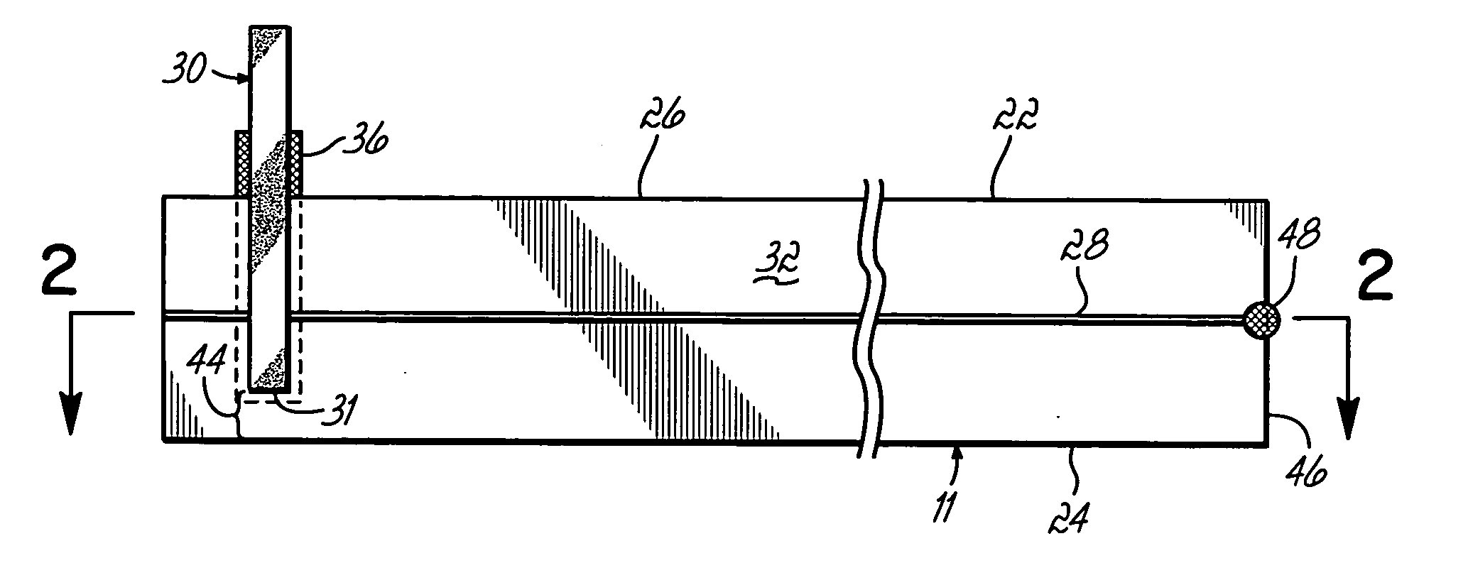
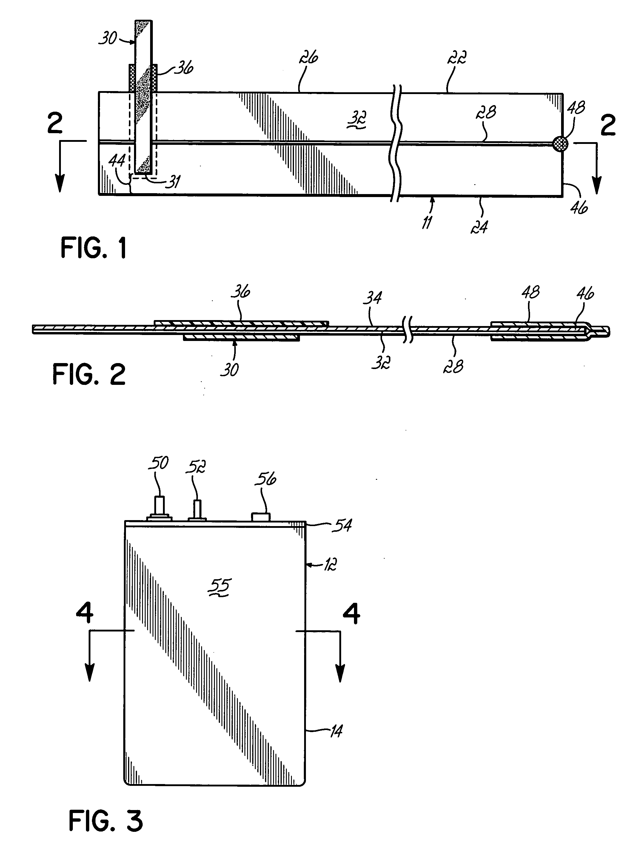
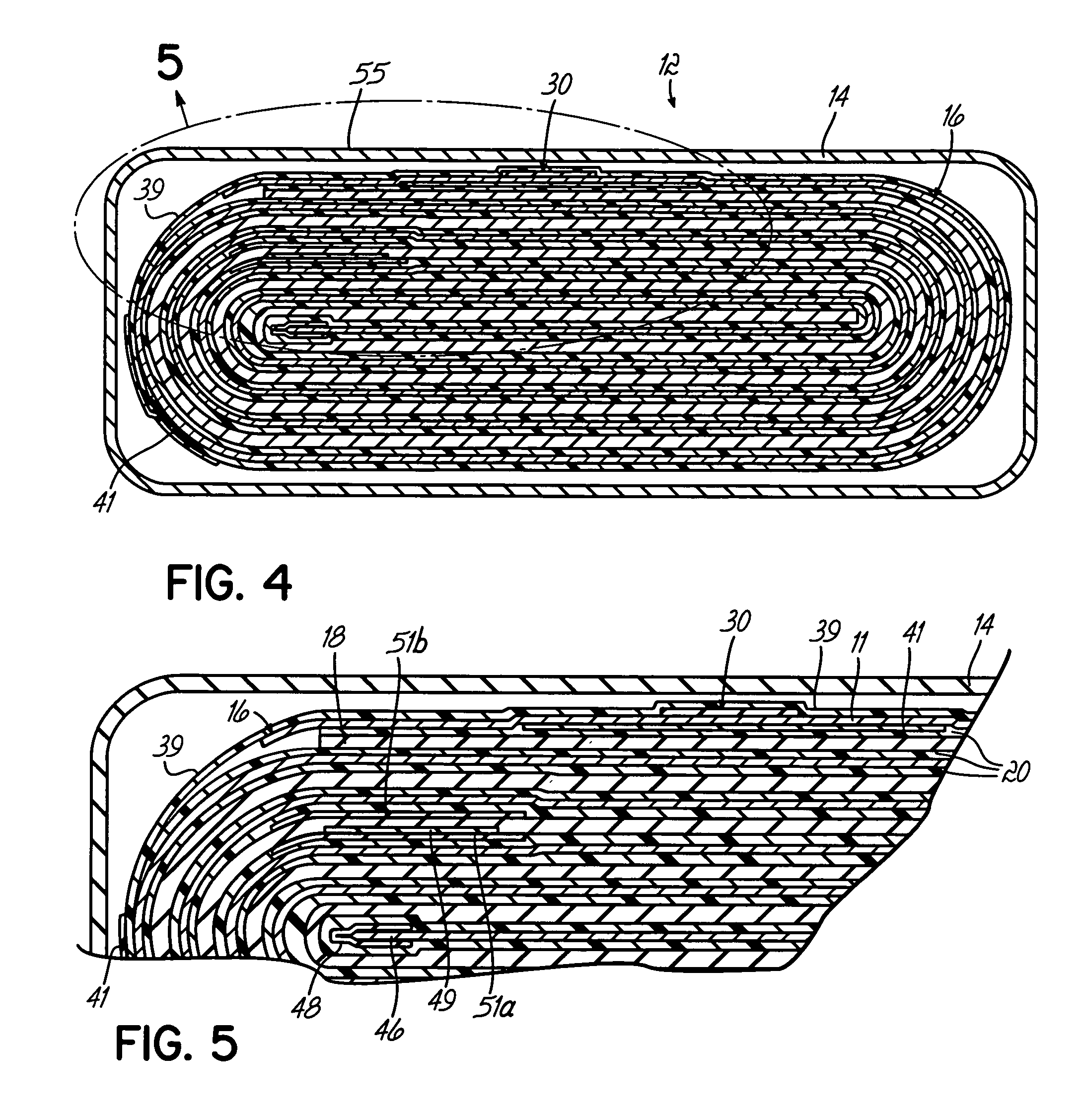
[0012] The present invention is an anode 11 as well as a prismatic cell 12 which is specially designed to reduce impedance as the cell is discharged. As shown in the Figures, the prismatic cell 12 includes a casing 14 which houses an anode / cathode roll 16. The anode / cathode roll 16 includes the anode 11, solid cathode 18 and a separator 20.

[0013] As shown more particularly in FIG. 1 and FIG. 2, the anode 11 includes an elongated metal strip 22 having a bottom edge 24 and a top edge 26. The anode is a reactive metal relative to the cathode active material. In the preferred embodiment, the metal is lithium. Running down the long axis of strip 22 is an embedded nickel wire 28 which acts as a current collector. More than one wire can be employed, if desired. An anode tab 30 is attached to a first side 32 of strip 22. As shown, this is attached by simply crimping portions of the nickel tab 30 into the metal strip 22.

[0014] The anode tab 30 extends partially down the width of the strip ...


PUM


Abstract

A prismatic cell for implantable medical devices includes an elongated anode and cathode folded together to form a prismatic cell. The anode includes an anode tab which does not extend to the bottom edge of the anode, with heat-resistant tape on the opposite side of the anode, likewise not extending to the bottom edge of the anode. This provides a strip of anode material below the anode tab which acts as a current collector reducing the increase in impedance as the cell is discharged.

Description

FIELD OF THE INVENTION [0001] The batteries which power implantable medical devices, such as cardiac defibrilators, must meet relatively demanding performance requirements. Power output to size is critical. As a result, many of these batteries are prismatically shaped, in other words, having a generally rectangular cross section with two elongated sides and two narrow sides. The cells are formed by an elongated anode and an elongated solid cathode with a separator between the two. These are wound or folded to assume the prismatic shape. A typical chemistry employed is lithium / manganese dioxide which uses a lithium anode, a manganese dioxide active material and an electrolyte. Other typical battery chemistries include Li / AgVO and Li / FeS2. [0002] These batteries include a cathode tab to connect the cathode to the positive terminal, and an anode tab to connect the anode to the negative terminal usually through the metal casing. [0003] The anode tab is a strip of conductive metal such a...

Claims


Application Information

Patent Timeline
IPC IPC(8): H01M4/02H01M4/50H01M4/505H01M4/75H01M10/04H01M10/052H01M10/0587H01M10/36H01M50/531H01M50/55H01M50/553H01M50/586H01M50/595
CPCH01M2/0217H01M2/26H01M2/30H01M2/34H01M2004/027H01M4/75H01M10/0431H01M10/052H01M10/0587H01M4/505Y02E60/10H01M50/103H01M50/531Y02P70/50H01M50/553H01M50/595H01M50/55H01M50/586
Inventor BRAND, CHRISTO
Owner EAGLE PICHER TECH LLC
Why Eureka
Try Eureka