Liquid crystal display device and method of fabricating the same
- Summary
- Abstract
- Description
- Claims
- Application Information
AI Technical Summary
Benefits of technology
Problems solved by technology
Method used
Image
Examples
first embodiment
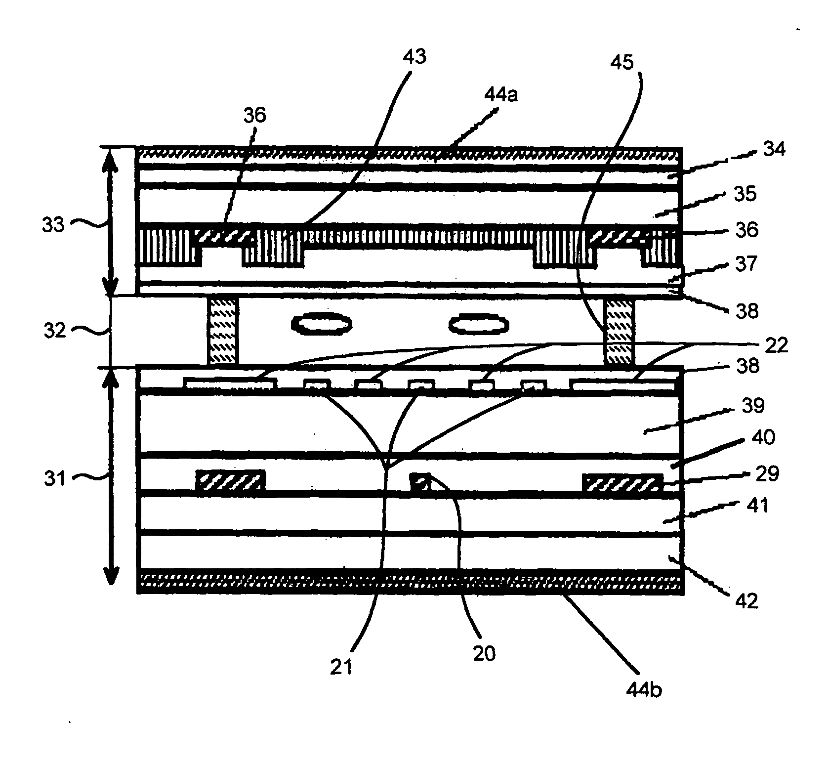
[0100]FIG. 3 is a plan view of an active device substrate in a liquid crystal display device in accordance with the first embodiment of the present invention, FIG. 4 is a cross-sectional view taken along the line IV-IV in FIG. 3, FIG. 5A is a cross-sectional view taken along the line VA-VA in FIG. 3, and FIG. 5B is a cross-sectional view taken along the line VB-VB in FIG. 3.
[0101] Hereinbelow is explained the liquid crystal display device in accordance with the first embodiment with reference to FIGS. 3, 4, 5A and 5B.
[0102] As illustrated in FIG. 4, the liquid crystal display device is comprised of an active device substrate 31, an opposed substrate 33 arranged in facing relation to the active device substrate 31, and a liquid crystal layer 32 sandwiched between the active device substrate 31 and the opposed substrate 33.
[0103] The opposed substrate 33 is comprised of a second electrically insulating transparent substrate 35, a black matrix layer 36 formed on the second electrica...
second embodiment
[0133]FIG. 6 is a plan view of an active device substrate in a liquid crystal display device in accordance with the second embodiment, FIG. 7A is a cross-sectional view taken along the line VIIA-VIIA in FIG. 6, and FIG. 7B is a cross-sectional view taken along the line VIIB-VIIB in FIG. 6.
[0134] Hereinbelow is explained the second embodiment with reference to FIGS. 6, 7A and 7B.
[0135] As illustrated in FIGS. 6, 7A and 7B, the electric-field shielding layer 60 in the second embodiment is designed not to have a cut-out 61. Accordingly, the liquid crystal display device in accordance with the second embodiment is structurally different from the liquid crystal display device in accordance with the first embodiment only in that the electric-field shielding layer 60 overlaps the thin film transistor 30.
[0136] Parts or elements that correspond to those of the first embodiment illustrated in FIGS. 3, 4, 5A and 5B have been provided with the same reference numerals.
[0137] The liquid crys...
example 1
[0139] Example 1 corresponds to the above-mentioned first embodiment.
[0140] Hereinbelow is explained a method of fabricating a liquid crystal display device in accordance with Example 1.
[0141] First, the active device substrate 31 is fabricated as follows.
[0142] On the first electrically insulating transparent substrate 42 is formed a chromium (Cr) film having a thickness of about 280 nm as a metal layer of which the scanning line 24 and the common electrode line 18 will be comprised later. Then, the chromium film is patterned.
[0143] On the chromium film are successively deposited the first interlayer insulating film 41 comprised of a silicon nitride film having a thickness of about 400 nm, the amorphous silicon (a-Si) film 25 having a thickness of about 200 nm, and an n-type amorphous silicon film having a thickness of about 30 nm. Then, the amorphous silicon (a-Si) film 25 and the n-type amorphous silicon film are patterned into an island.
[0144] Then, a chromium (Cr) film is ...
PUM
 Abstract
Description
Claims
Application Information
 - R&D
- Intellectual Property
- Life Sciences
- Materials
- Tech Scout
- Unparalleled Data Quality
- Higher Quality Content
- 60% Fewer Hallucinations
Browse by: Latest US Patents, China's latest patents, Technical Efficacy Thesaurus, Application Domain, Technology Topic, Popular Technical Reports.
© 2025 PatSnap. All rights reserved.Legal|Privacy policy|Modern Slavery Act Transparency Statement|Sitemap|About US| Contact US: help@patsnap.com


