Power transmission chain and power transmission apparatus using same

Inactive Publication Date: 2005-08-25
JTEKT CORP
View PDF19 Cites 35 Cited by
  • Summary
  • Abstract
  • Description
  • Claims
  • Application Information

AI Technical Summary

Benefits of technology

[0007] With the foregoing in view, it is an object of the present invention to provide a power transmission chain and power transmission device using same wherein the generation of noise can be effectively reduced.
[0009] According to the power transmission chain of the afore-mentioned configuration, since the contact point of the sheave faces with the pin end face is formed forward of the center position of the relevant end face in the direction of movement of the chain, the contact point moves in contact while forming a small angle in relation to the direction of the tangent from the pulley. Simultaneously with contact, the direction of movement of the contact point changes to the direction of the tangent from the pulley. In other words, the change in the angle of the contact point in relation to the pulley is reduced, and the contact noise associated with the change in angle can be reduced. Thus, the generation of noise can be reduced.

Problems solved by technology

However, in the afore-mentioned conventional chain-type CVT, when the chain pin end face and the sheave face are in contact, a contact noise is generated, constituting the cause of the noise of chain-type CVTs.
At this time, contact noise is generated in association with the changing of the angle in relation to the contact point of the pulley.
This contact noise increases as the change in the afore-mentioned angle increases.

Method used


Image

  • Power transmission chain and power transmission apparatus using same
  • Power transmission chain and power transmission apparatus using same
  • Power transmission chain and power transmission apparatus using same

Examples


first embodiment

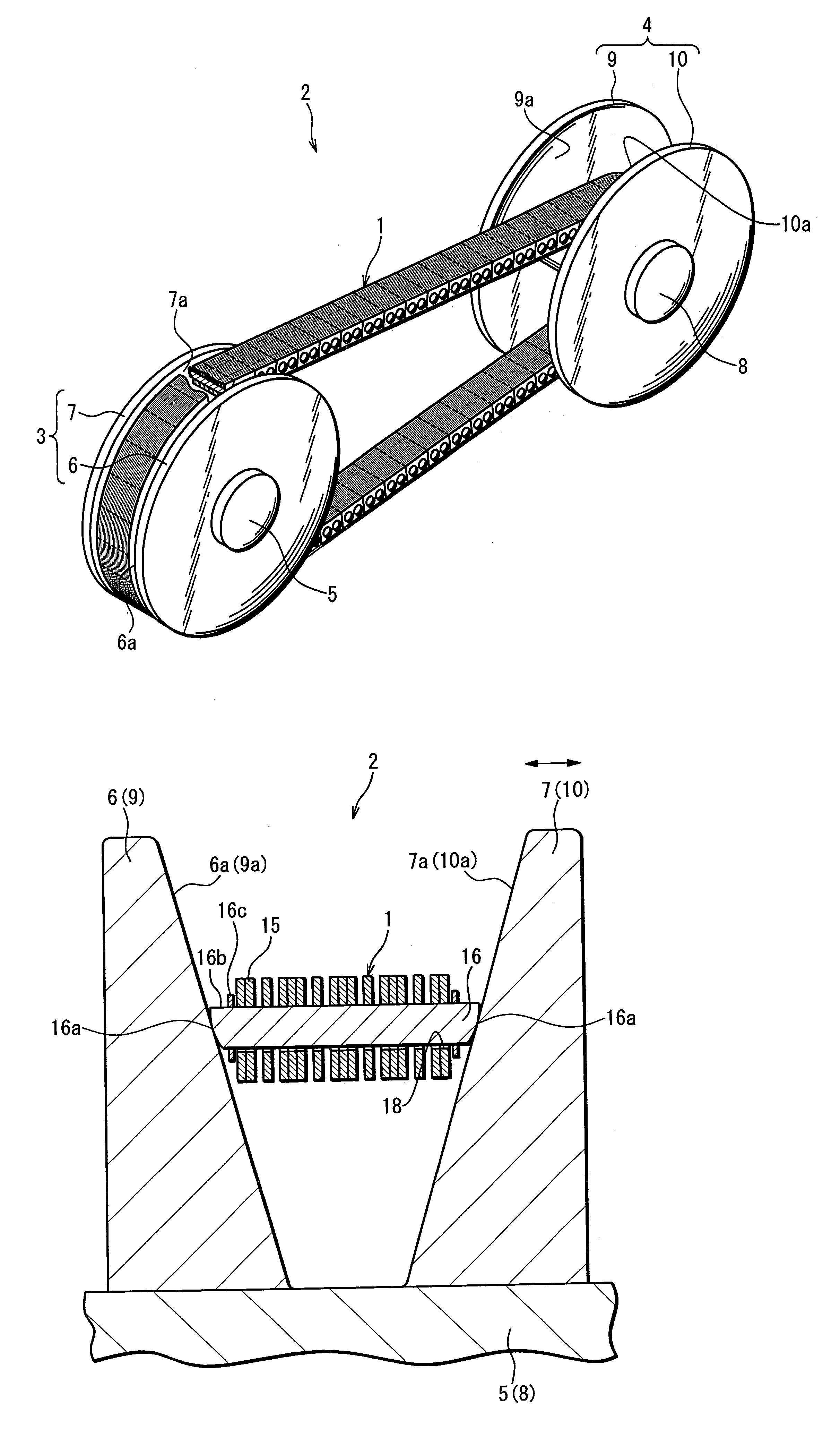
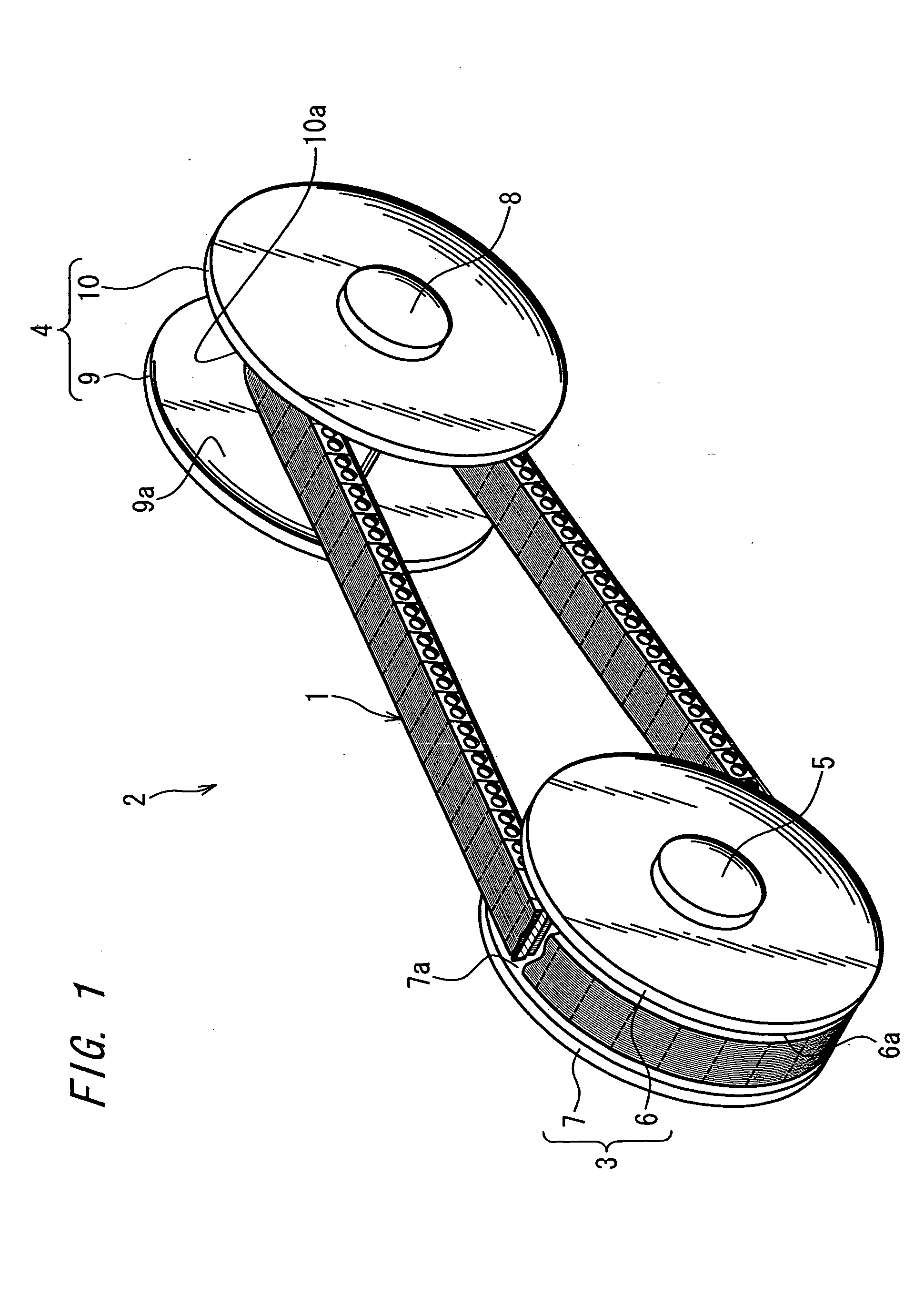
[0031]FIG. 1 shows the chain-type continuously variable transmission 2 (hereafter referred to simply as a ‘CVT’) wherein a power transmission chain 1 (hereafter referred to simply as a ‘chain’) related to the present invention is installed.

[0032] The CVT 2 is, for example, that mounted in a motor vehicle. This CVT 2 is provided with a metal (of structural steel and the like) drive pulley 3 as the first pulley, a metal (of structural steel and the like) driven pulley 4 as the second pulley, and an endless chain 1 spanning the first and second pulleys.

[0033] In FIG. 1, part of the chain 1 is sectioned to aid understanding.

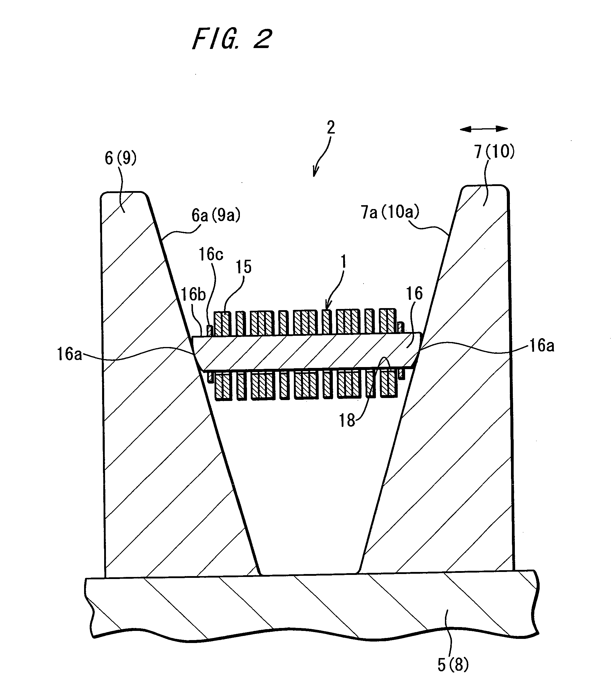
[0034] The drive pulley 3 is fitted integrally and rotatably to an input shaft 5 connected to a motor vehicle engine. This drive pulley 3 is provided with a fixed sheave 6 having a sheave face 6a of conical shape, and a movable sheave 7 having a sheave face 7a of conical shape positioned opposite this sheave face 6a.

[0035] The space between these sheave faces 6a a...

second embodiment

[0081] Formation of contact points P at random positions will be described in detail in the

[0082]FIG. 12 shows the relationship between the position of the contact points P1 through P4 on the X1 axis, and the amplitude on the Y2 axis.

[0083] As shown in FIG. 12, the amplitude in relation to the contact points P1 through P4 is approximately constant, and amplitude is unaffected even if the position of the contact point P is changed. In other words, contact noise can be effectively reduced without amplifying the amplitude associated with polygonal movement.

[0084]FIG. 13 is a graph showing the sound pressure level at each frequency when the contact point P is displaced by 1 mm from the center position C of the pin end face 16a forward in the direction of movement of the chain.

[0085]FIG. 14 is a graph showing the case wherein the contact point P is provided at the center position C of the pin end face 16a. The dashed lines shown in FIG. 13 and FIG. 14 show the fundamental frequency (1...

third embodiment

[0103]FIG. 16 shows the essential components of the power transmission chain 1 related to the present invention.

[0104] The present embodiment differs from other embodiments in that the links 15 are comprised of at least two types wherein the link pitch Rp differs, for example, link 15A and link 15B, and arranged such that the distance between these links 15A and 15B and the adjacent pin 16 Pp (contact point pitch) is random.

[0105] The link pitch Rp noted here is the distance between pins 16 inserted through through-holes 18A and 18B in the same link 15. This link pitch Rp is the distance between the contact points S of the pin 16 and strip 17. This link pitch Rp is measured with the chain 1 in a straight (not curved) condition.

[0106] As shown in FIG. 16, the position of the contact point P of the pin end face 16a is the same for all pins 16. The link pitch Rp for link 15A is slightly greater than for link 15B. In the chain 1 of the present embodiment, a plurality of links 15B are ...


PUM


Abstract

This power transmission chain has a plurality of links, and a plurality of pins mutually joining this plurality of links. The power transmission chain is used to span a first pulley having a sheave face of conical shape, and a second pulley having a sheave face of conical shape, and power is transmitted by contact of both end faces of the pins, and the sheave faces of the first and second pulleys. Contact points are formed at both ends of this pin such as to contact the sheave face forward of the center position of the relevant end face.

Description

FIELD OF THE INVENTION [0001] The present invention relates to a power transmission chain and power transmission device using same employed in a chain-type continuously variable transmission (CVT) and the like employed in vehicles and the like. DESCRIPTION OF THE PRIOR ART [0002] A motor vehicle CVT is provided with, for example, a drive pulley fitted to the engine, a driven pulley fitted to the drive wheel, and an endless chain spanning both pulleys. The afore-mentioned chain has a plurality of links, and a plurality of pins mutually joining these links, and a plurality of strips. [0003] In the chain-type CVT related to the afore-mentioned configuration, the sheave face of conical shape of each pulley and the chain pin end faces are in slight sliding contact in the circumferential direction of the sheave face. Thus, traction is generated and power torque is transmitted. The chain-type CVT is able to continuously vary speed by continuously varying the width of the groove (distance b...

Claims


Application Information

Patent Timeline
IPC IPC(8): F16G5/18
CPCF16G5/18
Inventor LOU, LIMING
Owner JTEKT CORP
Why Eureka
Try Eureka