
Methods and systems for differentiating left and right eye images

a technology of left and right eye surgery and imaging methods, applied in the field of laser eye surgery methods and systems, can solve the problems of confusion between wavefront measurement images of left eyes and wavefront images of right eyes, errors may occur, and the wavefront measurement system alone cannot eliminate all potential errors of laser eye surgery procedures

Inactive Publication Date: 2005-08-25
AMO MFG USA INC
View PDF79 Cites 13 Cited by
  • Summary
  • Abstract
  • Description
  • Claims
  • Application Information

AI Technical Summary

Benefits of technology

[0017] In another aspect of the present invention, a laser eye surgery system includes: a laser emitting a beam of an ablative light energy; a light source directing light toward a corneal tissue of the eye; a microscope capturing an image of the illuminated corneal tissue; and a computer processor configured to direct a customized pattern of the ablative light energy toward the eye, the processor having a left/right eye identification module generating either a left eye signal or a right eye signal in response to the corneal tissue image. In some embodiments, the module generates an indeterminate eye signal

Problems solved by technology

Of course, wavefront measurement systems alone cannot eliminate all potential error from a laser eye surgery procedure.
Errors may occur, for example, in transferring information from the measurement system to the ablation system or in the operation of the ablation system.
One possible error that may be made is that a wavefront measurement image of a left eye may be confused with a wavefront image of a right eye.
This may occur due to a mislabeling of the images, misinterpretation of the images by an operator of the ablation system, or the like.

Method used


Image

  • Methods and systems for differentiating left and right eye images
  • Methods and systems for differentiating left and right eye images
  • Methods and systems for differentiating left and right eye images

Examples


Embodiment Construction

[0023] The present invention is particularly useful for enhancing the safety and accuracy of laser eye surgical procedures such as photorefractive keratectomy (PRK), phototherapeutic keratectomy (PTK), laser in situ keratomileusis (LASIK), and the like. Safety and accuracy is enhanced by distinguishing right eye images from left eye images, to help ensure that an eye treatment plan is matched with a proper eye. While the system and methods of the present invention are described primarily in the context of improving laser eye surgery methods and systems, various embodiments may also be adapted for use in alternative eye treatment procedures and systems such as femtosecond lasers and laser treatment, infrared lasers and laser treatments, radial keratotomy (RK), scleral bands, follow up diagnostic procedures, and the like.

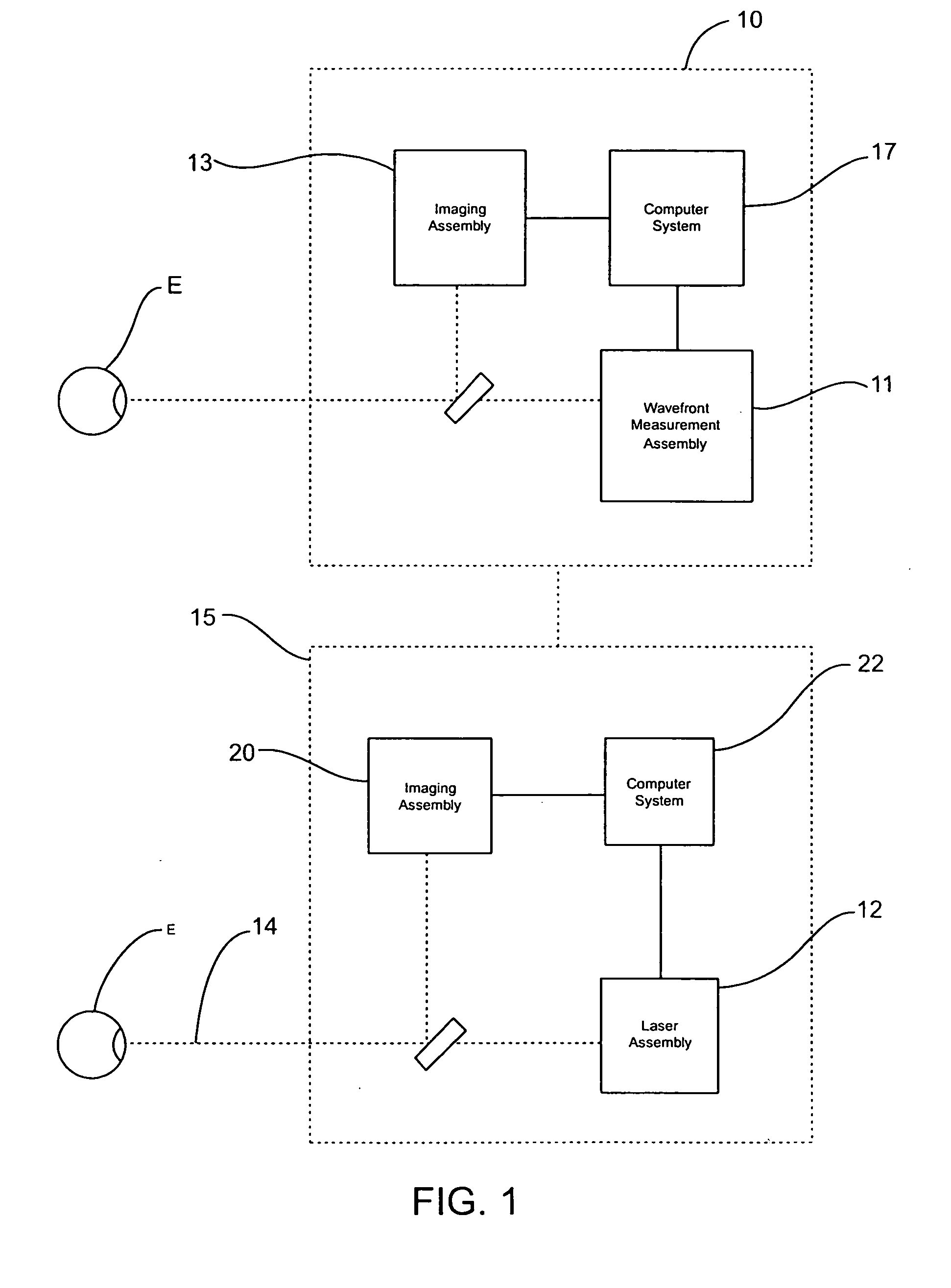
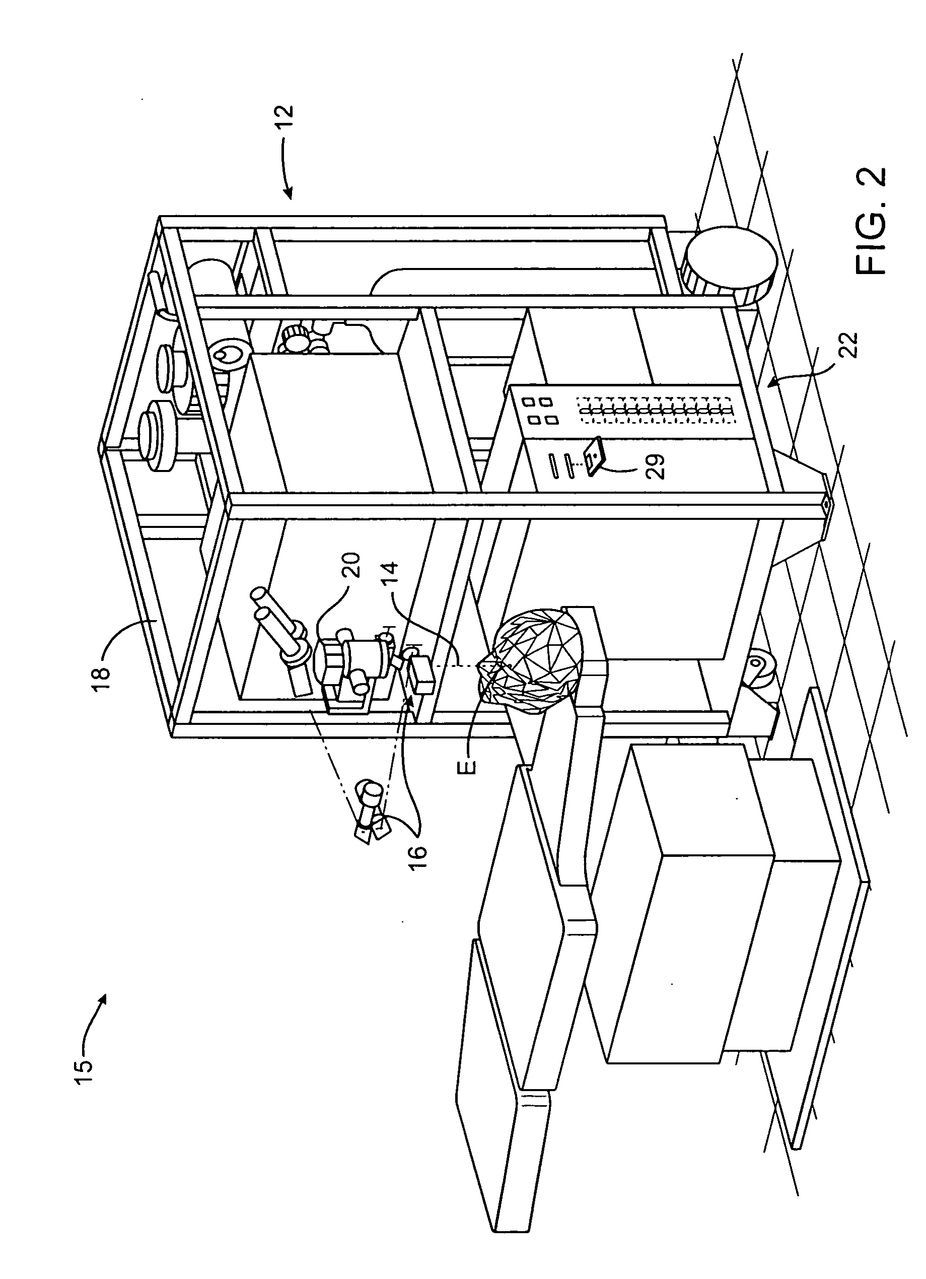
[0024] Referring to FIG. 1, one embodiment of a system for performing laser eye surgery includes a laser system 15 coupled to a wavefront measurement device 10 that ...


PUM


Abstract

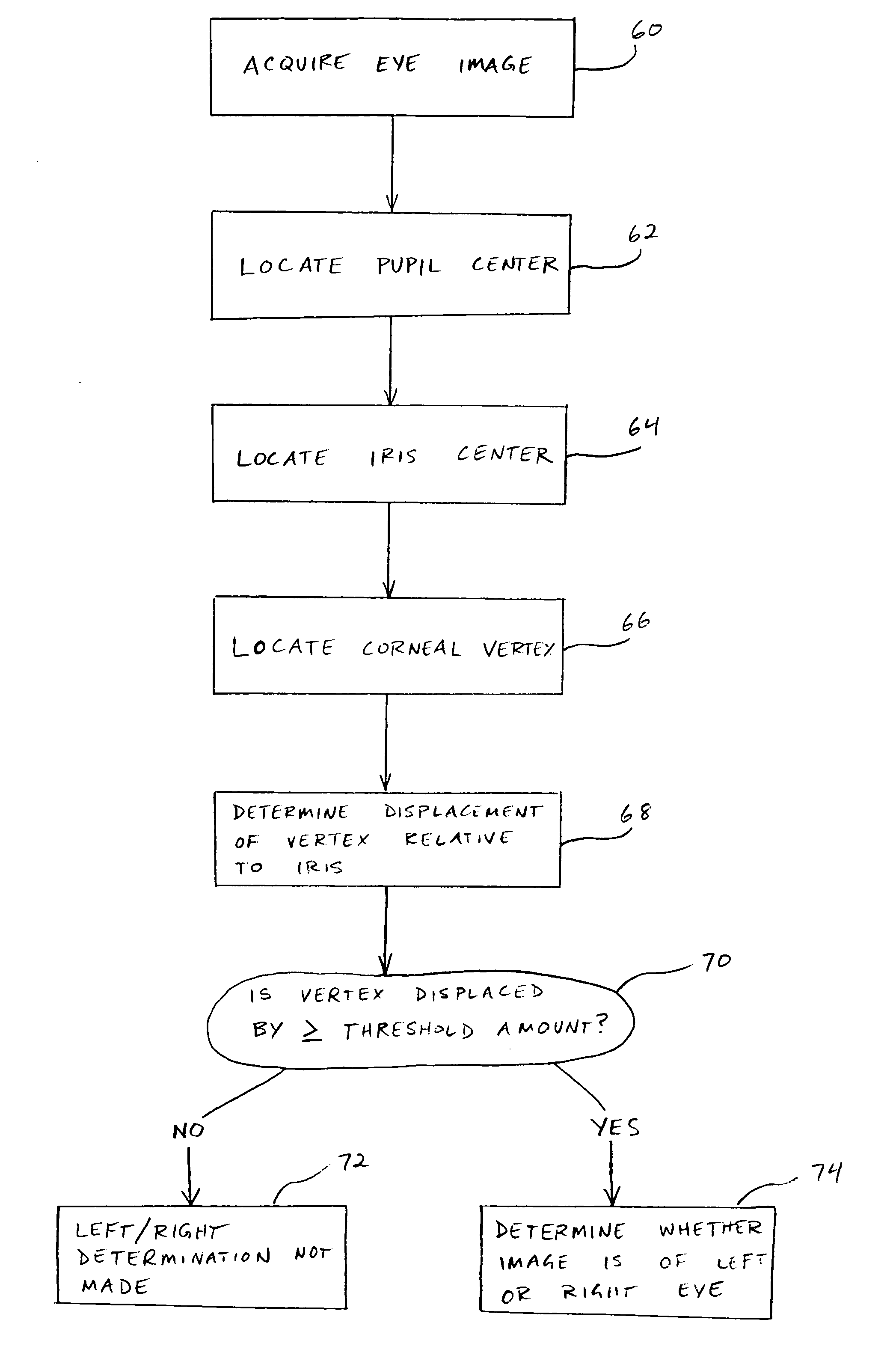
Methods and systems for determining whether an image is of a left eye or a right eye may be used to enhance laser eye surgery systems and techniques. Methods generally involve locating an iris center and / or pupil center on an image of the eye, locating a corneal vertex and / or at least one reflection on the image, and determining whether the image is of a left eye or a right eye, based on the location of the corneal vertex and / or reflection(s) relative to the iris center and / or pupil center. Systems include a laser emitting a beam of an ablative light energy and a computer processor having a computer program for determining whether the image is of a left eye or a right eye, based on a location of the corneal vertex and / or reflection(s) relative to the iris center and / or pupil center.

Description

CROSS-REFERENCE TO RELATED APPLICATIONS [0001] The present application is related to U.S. patent application Ser. No. 10 / 300714 (Attorney Docket No. 18158-021510US), filed Nov. 19, 2002, and Ser. No. 10 / 460060 (Attorney Docket No. 18158-020410US), filed Jun. 11, 2003, the full disclosures of which are hereby incorporated by reference.BACKGROUND OF THE INVENTION [0002] The present invention relates generally to laser eye surgery methods and systems. More specifically, the present invention relates to methods and systems for differentiating between left and right eye images. [0003] Known laser eye procedures generally employ an ultraviolet or infrared laser to remove a microscopic layer of stromal tissue from the cornea of the eye to alter the refractive characteristics of the eye. The laser removes a selected shape of the corneal tissue, often to correct refractive errors of the eye. Ultraviolet laser ablation results in photo-decomposition of the corneal tissue, but generally does n...

Claims


Application Information

Patent Timeline
IPC IPC(8): A61B3/00A61B3/10A61F9/008
CPCA61B3/10A61B3/1015A61F9/008A61F9/00802G06K9/00899A61F2009/00846A61F2009/00872A61F2009/0088G06K9/00604A61F9/00825G06V40/19G06V40/40
Inventor WONG, JONATHANCHERNYAK, DIMITRI
Owner AMO MFG USA INC
Learn More