Eureka AIR delivers breakthrough ideas for toughest innovation challenges, trusted by R&D personnel around the world.

Planar antenna and antenna system

Inactive Publication Date: 2005-08-25
VEGA GRIESHABER GMBH & CO
View PDF3 Cites 16 Cited by
  • Summary
  • Abstract
  • Description
  • Claims
  • Application Information

AI Technical Summary

Benefits of technology

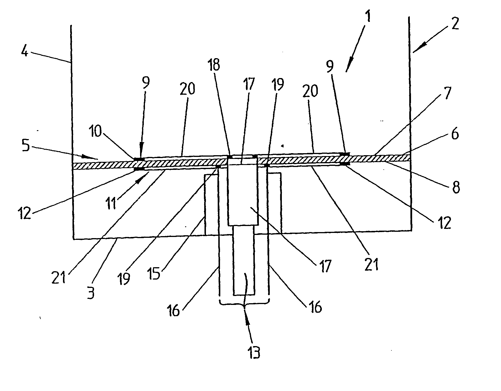
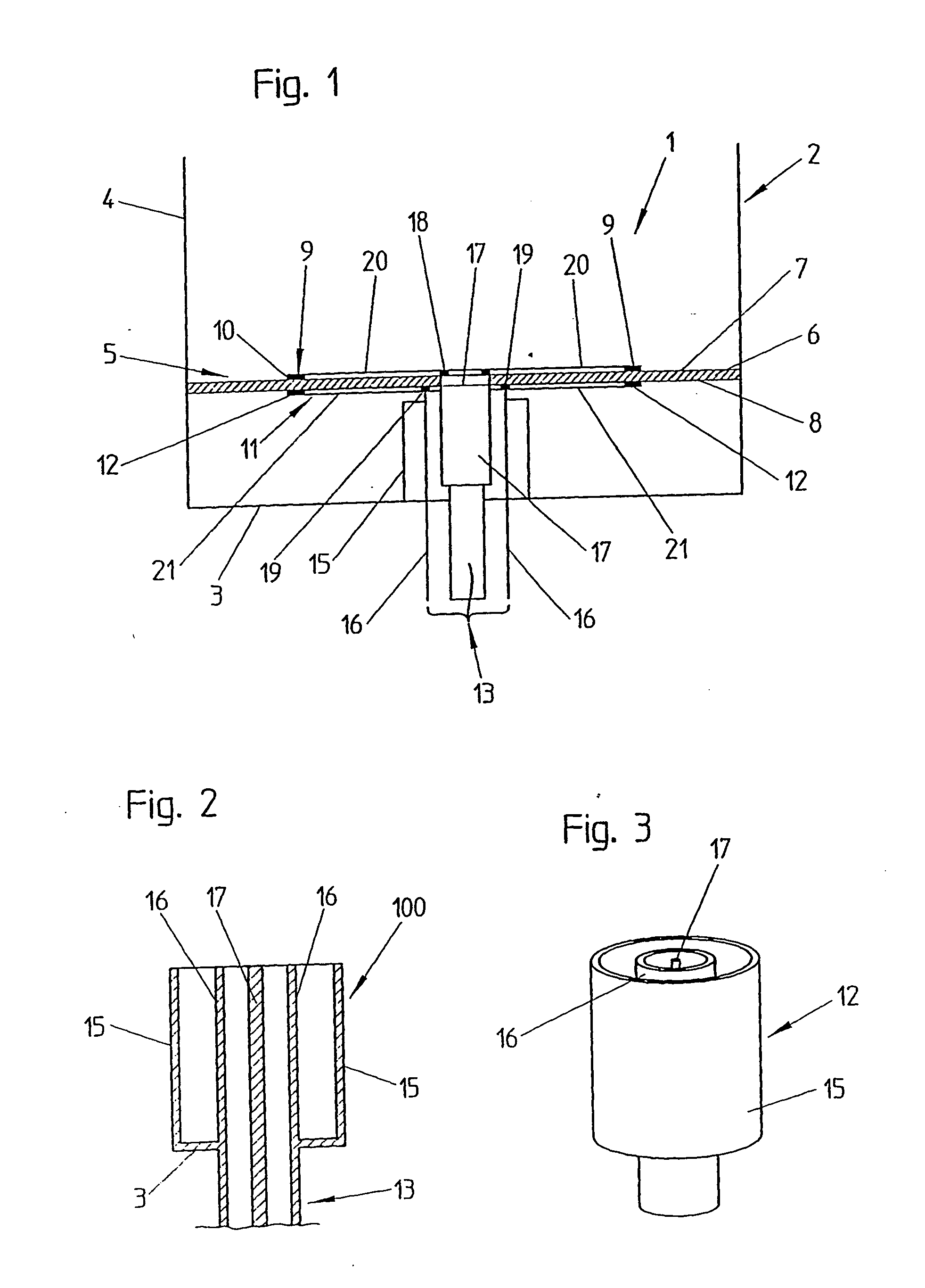
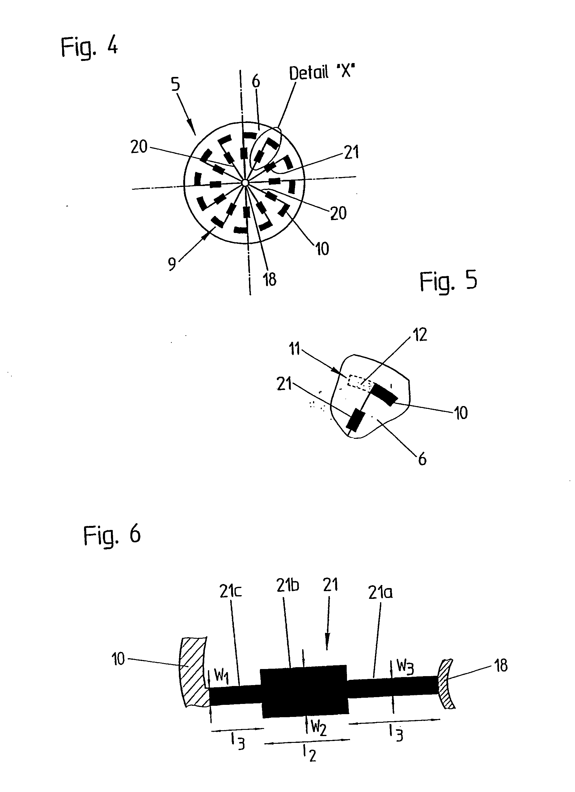
[0020] Due to easier manufacturing, in an exemplary embodiment of a planar antenna according to the present invention the first group of dipole arms and the second group of dipole arms are arranged on different surfaces of the substrate. Hence, the first group of dipole arms may be arranged on the upper surface intended to face towards the filling good, and the second group of dipole arms is arranged on the lower surface of the substrate intended to face towards a bottom plate of a waveguide-tube. Such an arrangement of dipole arms allows the arrangement a relatively high number of dipole arms on each surface without the problem that the excitation structures come too close to one another. Furthermore, a central feeding may be provided for the first group of dipole arms and for the second group of dipole arms. A feeding might be provided by a first connection element from which dipole arm connection portions extend up to the dipole arms. A second connection element may be provided on the other surface of the substrate to connect the dipole arms of the other group.
[0025] In a further exemplary embodiment of the antenna system according to the present invention, the spacing between the bottom plate of the waveguide tube and the second surface of the substrate is partly or completely filled with at least one dielectric material. The dielectric material may be Teflon, PTFE or Rohacell. Due to the dielectric material partly or completely filling the spacing, the strength of the whole assembly is improved.

Problems solved by technology

Horn antennas and the use of the fundamental TE11-mode allow high resolution and high accuracy, but there are limitations due to the influence of the wall material of the measuring pipes.
The bypass holes may cause false echoes, disturb the measurement and may decrease the accuracy.

Method used


Image

  • Planar antenna and antenna system
  • Planar antenna and antenna system
  • Planar antenna and antenna system

Examples


second embodiment

[0057] In FIG. 9, several various embodiments of an antenna system according to the invention are shown. For simplification of the drawings, only the substrate 6 and the waveguide-tube 2 are shown. In the first exemplary embodiment of the invention, a covering layer 40 is provided directly on the substrate 6. The covering layer 40 is of a dielectric material. In the second embodiment, a covering layer 41 is arranged at a distance to the substrate 6. The third and fourth exemplary embodiments show a covering layer 42, 43 arranged at a distance to the substrate 6 but having a convex or conical shape.

sixth embodiment

[0058] The fifth and sixth embodiment of the present invention show a covering layer 44 and 45 arranged on the substrate 6. Again, the covering layers 44, 45 have a conical or convex shape.

[0059] The last embodiment comprises a covering layer 46 including two or more different layers 46a, 46b. The outer layer 46b has a convex or concave shape.

[0060] The material of the covering layer has to be a dielectric material, as, for example, PTFE. The thickness of such a layer may be approximately λ / 4 or n×λ / 4, wherein n∈N.

[0061] Finally, we refer to FIG. 10 showing a schematic cross section of an antenna system 1 according to the present invention. Here, the planar antenna 5 is arranged as mentioned above within the waveguide-tube 4. A bypass-tube 45 is connected with the waveguide-tube 4 by a taper 44. The taper serves to match the inventive antenna system 1 with the bypass-tube 45 having a diameter larger than the diameter of the waveguide-tube 4.

[0062] If the diameter of the bypass-tu...


PUM


Abstract

The present invention relates to a planar antenna (1) for excitation of the TE01-mode of an electromagnetic wave and adapted to be arranged in a waveguide tube (2). The planar antenna comprises a substrate (6) of dielectric material having a first surface (7) intended to face towards a filling good surface and a second surface (8) facing in an opposite direction. A first group (9) of a plurality of dipole arms (10) is arranged on the first surface (7) or the second surface (8) on a perimeter of a circle with a predetermined radius. A second group (11) of a plurality of dipole arms (12) is arranged on the first surface (7) or the second surface (8) on the perimeter of the circle with the predetermined radius. The dipole arms (10) of the first group (9) extend in a first direction and the dipole arms (12) of the second group (11) extend in a direction opposite the first direction. Furthermore, the present invention relates to an antenna system comprising a cylindrical waveguide tube (2) having a bottom plate (3) and a tube portion (4) and a planar antenna (1) as mentioned above.

Description

FIELD OF THE INVENTION [0001] The invention relates to a planar antenna for exciting the TE01-mode (also known as H01-mode) and intended to be used in a filling level measuring device for determining a filling height of a filling good in a receptacle. The present invention relates furthermore to an antenna system adapted to be used in a tube, e.g. a bypass tube, for measuring the height of a filling good in a receptacle. [0002] The “genuine radar method” (also called pulse radar method) and the “time domain reflectometry (TDR)-Method” generate electromagnetic waves or measuring signals which are transmitted in the direction of the surface of a medium or filling good and are at least partially reflected at the surface of the medium as so-called echo signals. The echo signals are detected and evaluated by means of a delay time method. These techniques are well known and, therefore, detailed explanations are omitted. These basic methods are, for example, explained in “Radar Level Measu...

Claims


Application Information

Patent Timeline
IPC IPC(8): H01P5/10H01Q1/22H01Q1/38H01Q9/06H01Q9/28H01Q13/06H01Q13/18H01Q21/06H01Q21/20
CPCH01P5/10H01Q1/225H01Q21/20H01Q9/285H01Q21/062H01Q9/065
Inventor MAHLER, WOLFGANGLANDSTORFER, FRIEDRICHMOTZER, JURGEN
Owner VEGA GRIESHABER GMBH & CO
Why Eureka
Eureka Blog
Learn More