
Catheter and cable inspection system and method

Inactive Publication Date: 2005-08-18
ALLIANCE MEDICAL
View PDF1 Cites 16 Cited by
  • Summary
  • Abstract
  • Description
  • Claims
  • Application Information

AI Technical Summary

Benefits of technology

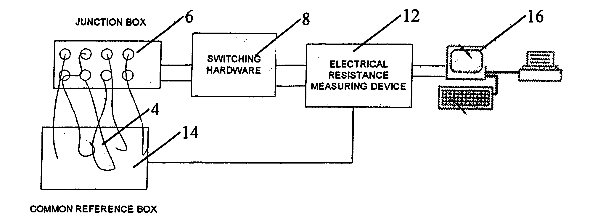
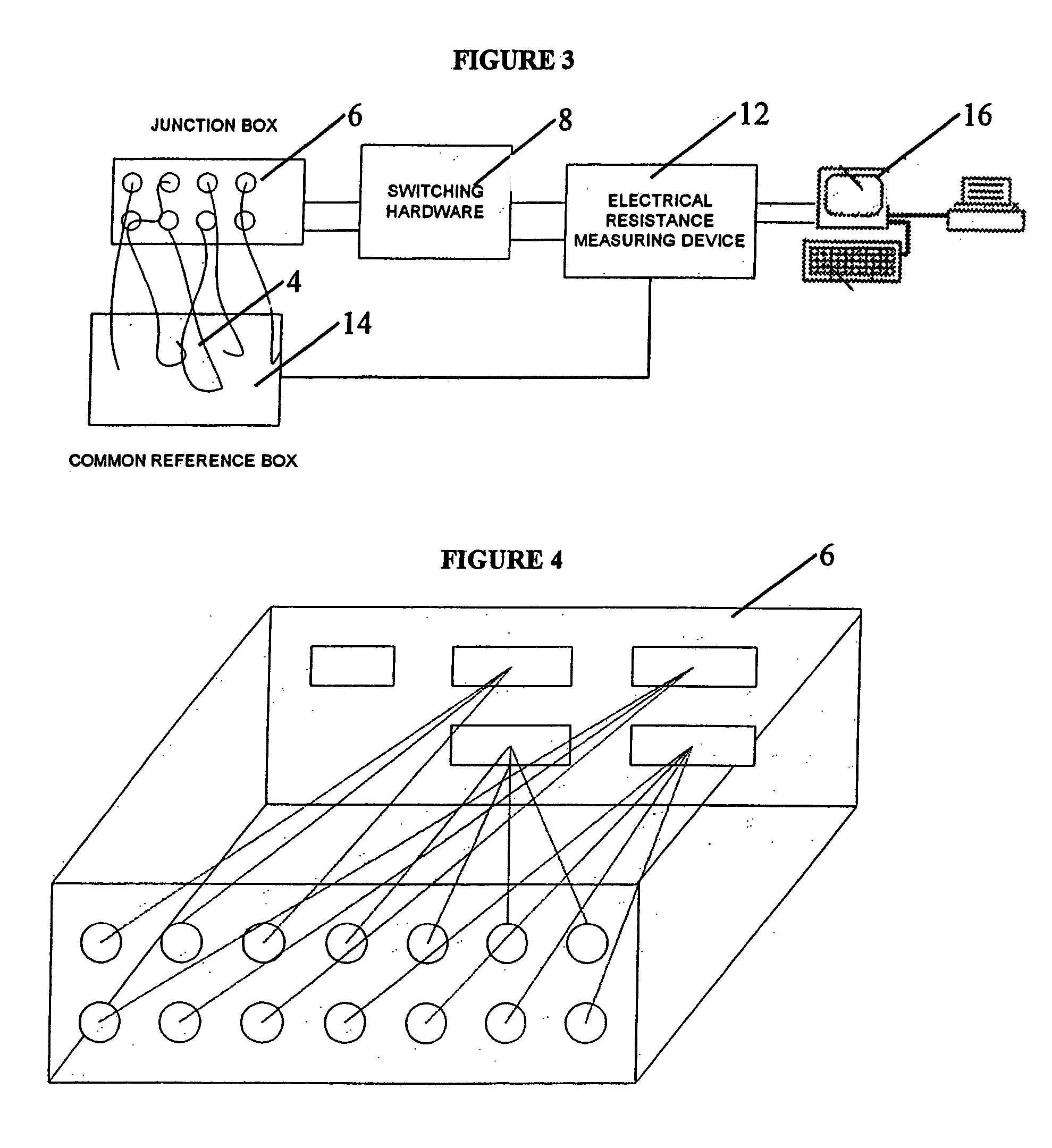
[0011] The present invention includes an exemplary system which facilitates automation of a practical electrical continuity test to determine the extent of functionality of an EP catheter and / or cable. An exemplary embodiment of the system is to provide a system for testing the electrode catheter / cable so that its functionality can be determined for making multiple uses of the catheter / cable possible. The system of the present invention utilizes, for example, a computer, an electrical resistance measuring device, switching hardware, software program, Junction hardware and a novel support structure for providing common connection between one of the probes of the measuring device and multiple catheters having variable number of electrodes with variable electrode pacing.

Problems solved by technology

Sterilization just prior to re-use eliminates or minimizes the catheter / cable microbes, whereupon when properly and rigorously cleaned, re-use of catheters and cables did not create an obvious increase in the risk of infection.
However, it has also been found that repeated sterilization may make the catheter and its electronic components fragile, thereby possibly leading to the deterioration of the mechanical and electrical properties of the catheter.
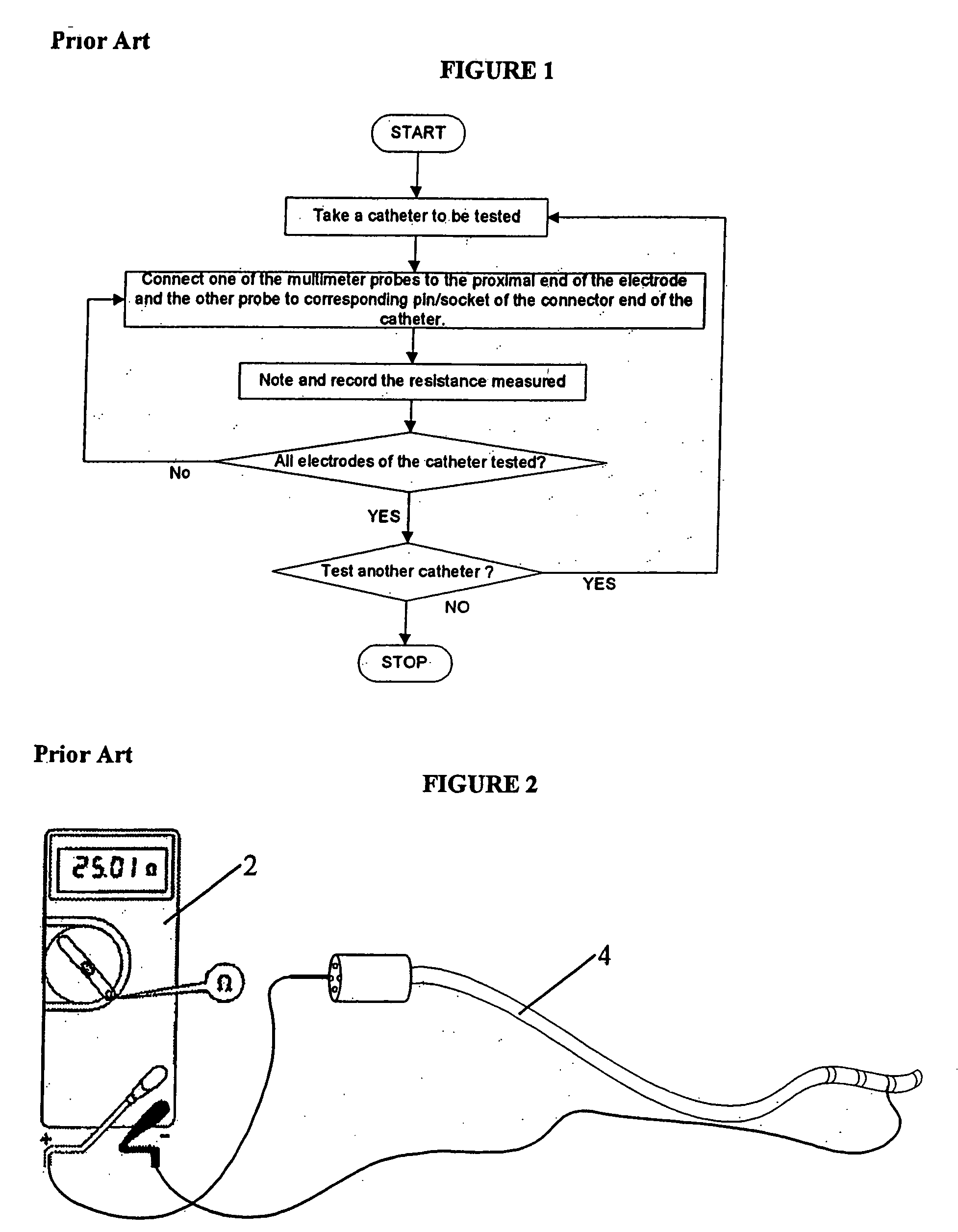
The above described test procedure usually includes both hands to adequately hold the probes in place and to manipulate the probes properly, and becomes rather cumbersome to carry out testing adequately.
Also, when attempted manually, the probes may not make proper contact with the elements against which they are placed, possibly resulting in false positive or negative readings.
A false negative reading can result in discarding a perfectly functional catheter.
A false positive reading can result in inserting a defective catheter into the artery of a patient.
The situation may be further complicated by the variety of catheters commercially available to medical practitioners and of the variations in electrode size, spacing and characteristics.

Method used


Image

  • Catheter and cable inspection system and method
  • Catheter and cable inspection system and method
  • Catheter and cable inspection system and method

Examples


Embodiment Construction

[0030] The detailed description of exemplary embodiments of the invention herein makes reference to the accompanying drawings and pictures, which show an exemplary embodiment by way of illustration and its best mode. While these exemplary embodiments are described in sufficient detail to enable those skilled in the art to practice the invention, it should be understood that other embodiments may be realized and that logical and mechanical changes may be made without departing from the spirit and scope of the invention. Thus, the detailed description herein is presented for purposes of illustration only and not of limitation. For example, the steps recited in any of the method or process descriptions may be executed in any order and are not limited to the order presented.

[0031] An exemplary embodiment of the present invention is to provide an automated testing system for testing of electrophysiology catheters / cables and facilitate a technician to rapidly and accurately test a large ...


PUM


Abstract

The invention includes an automated inspection system, which automates the evaluation of electrical integrity to determine whether electrode catheters and / or cables are functioning properly. An exemplary embodiment of the system is to provide a system and method for automating the testing of various electrical parameters of several electrode catheters and / or cables so that its performance can be evaluated. The automated inspection system also automates, for example, catheter / cable identification, analysis to known specifications, and report printing and recording of the data analyses.

Description

CROSS REFERENCE TO RELATED APPLICATION [0001] This application claims the benefit of, and priority to, provisional application Ser. No. 60 / 510,462, filed Oct. 10, 2003, which application is hereby incorporated by reference in its entirety.FIELD OF THE INVENTION [0002] The present invention relates to automated test equipment, including computerized equipment for testing electrode catheters and cables (e.g. electrophysiology diagnostic or therapeutic catheters, anatomic signal recording devices, electrocoagulation or electrocautery devices and cables, or the like). More specifically, this invention pertains to an automated, high volume process for detecting, identifying and quantifying electrical viability of reprocessed electro-physiology catheters and cables. BACKGROUND OF THE INVENTION [0003] Electro-physiology catheters and other electrical transmission devices typically consist of a central core of wires terminating at one end with one or more electrodes, and at the opposite end...

Claims


Application Information

Patent Timeline
IPC IPC(8): A61N1/00A61N1/04A61N1/05A61N1/06A61N1/08
CPCA61N2001/083A61N1/08G01R31/54G01R31/58A61B2560/0276A61B5/276A61B5/287A61B5/283
Inventor MAHAJAN, ATUL
Owner ALLIANCE MEDICAL
Learn More