Protection for bi-directional optical wavelength division multiplexed communications networks

Inactive Publication Date: 2005-08-18
GO4FIBER
View PDF10 Cites 38 Cited by
  • Summary
  • Abstract
  • Description
  • Claims
  • Application Information

AI Technical Summary

Benefits of technology

[0008] According to one aspect of the invention, it provides a bi-directional WDM optical communications network having a protection switching capability within two bi-directional optical waveguides, wherein the transmission scheme can accommodate one or more optical signals at distinct wavelengths or bands of wavelengths, each of which can accommodates one or more channels, comprising: (a) two node disjoint bi-directional optical waveguides, each of which is configured to carry one or more of the counterpropagating WDM optical communications signals; (b) optical signal transmitting means, at each end of the network, for transmitting one or more of the WDM optical communications signals having distinct wavelengths or bands of wavelengths; (c) optical signal receiving means, at each end of the network, for receiving one or more WDM optical communications signals having distinct wavelengths or bands of wavelengths other than the wavelengths or bands of wavelengths of the signals sent by the transmitting means located at the same end of the network as said receiving means; (d) coupling means, at each end of the network, for adding the optical signals of the transmitting means at that end of the network to the waveguide and removing the optical signals received at the same end of the network from the waveguide; and (e) waveguide failure detection means, connected to the coupling means at each end of the two bi-directional optical waveguides, for detecting a failure of one of the wa

Problems solved by technology

This prior art also explains the difficulties of bi-directional link protection, caused by a loopback silent failure that prevents restoration of the transmission path by switching to a secondary fiber link.

Method used


Image

  • Protection for bi-directional optical wavelength division multiplexed communications networks
  • Protection for bi-directional optical wavelength division multiplexed communications networks
  • Protection for bi-directional optical wavelength division multiplexed communications networks

Examples


Embodiment Construction

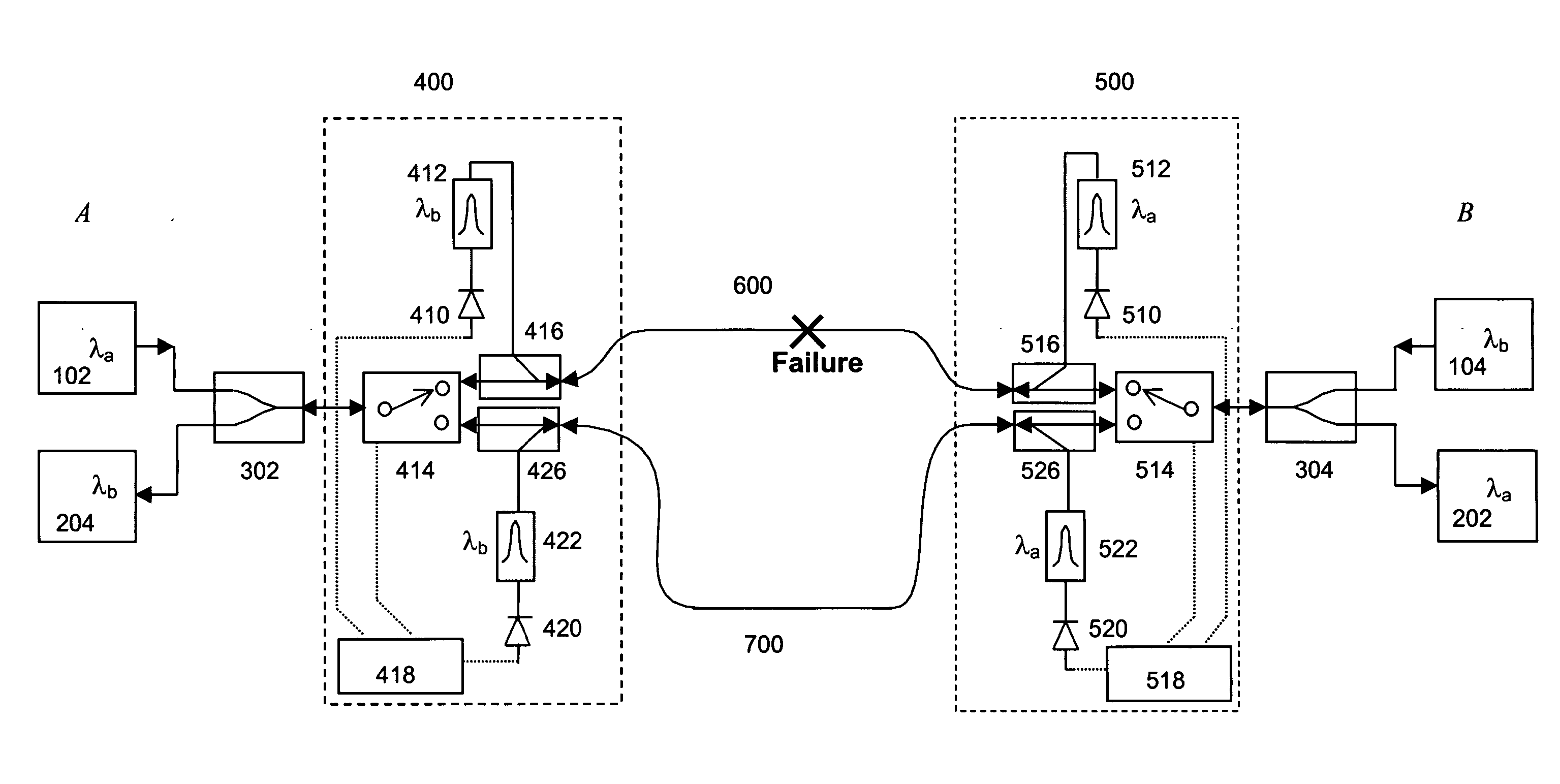
[0014] The present invention is a kind of APS implementation focused on bi-directional optical transmission systems. The network protected in such a way is able to recognize and respond to fault conditions as soon as they occur. While the discussion is focused on all optical networks, it applies, more generally, to networks incorporating any type of switching, transmission and other communications technology and signal multiplexing scheme, protocol or technology.

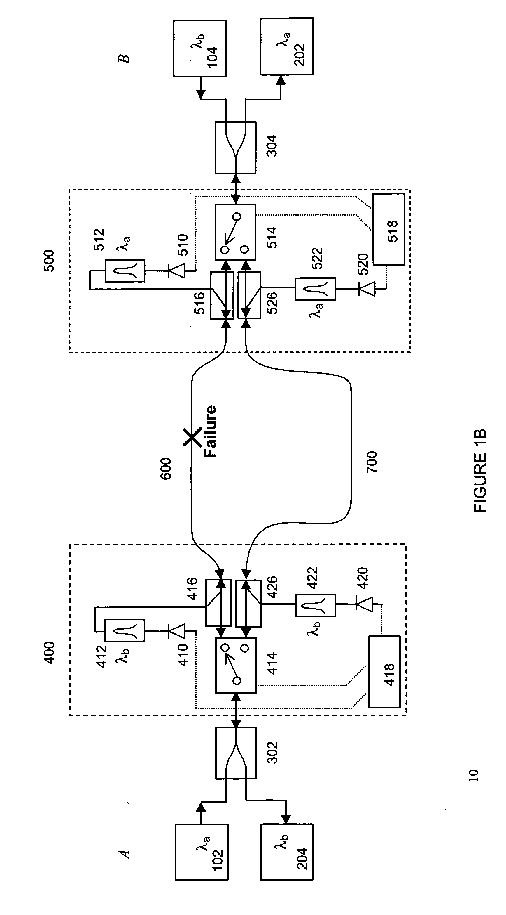
[0015] Turning to the drawings in detail, FIG. 1A depicts a bi-directional WDM optical communications network 10 according to one embodiment of the invention. The bi-directional WDM optical network includes two bi-directional waveguides 600 and 700, each of which is configured to carry counter-propagating WDM optical communications signals, each comprising plural optical channels at different channel wavelengths. In accordance with traditional industry nomenclature, the WDM signals propagating in a first direction and havin...


PUM


Abstract

A bi-directional wavelength division multiplexed (WDM) optical communications network that includes components for automatically detecting a fault along a primary optical waveguide in a link forming part of a bi-directional WDM communication network and switching the transmission path of the optical signals propagated along that link from that waveguide to a second standby waveguide whenever a fault is detected in the first waveguide using 1×2 optical switches, optical filters, photodetectors and electronics in a configuration designed to avoid silent event failures. Replacing the 1×2 optical switches with 2×2 optical switches in conjunction with other equipment can allow either the constant monitoring of the standby waveguide, provide back up for optical transmitters, receivers and couplers on the path containing the primary waveguide and / or allow carriage of low priority traffic on the standby waveguide as long as it is in standby mode. No handshaking mechanism is required between the opposite ends of the waveguides for the switchover protection.

Description

FIELD OF THE INVENTION [0001] The present invention relates to optical communications networks in general and, more particularly, to bi-directional optical communications networks in which two wavelength division multiplexed (WDM) optical signals propagate in opposite directions on a bi-directional waveguide. Following a waveguide failure (such as a fiber optic cable cut or other equipment failure), optical traffic is re-routed by a switching protection mechanism to a second bi-directional waveguide in order to avoid an interruption in the propagation of the optical signals. BACKGROUND OF THE INVENTION [0002] Optical communication transmission systems operate at high speeds and carry large volumes of traffic of various kinds. Presently, fiber optic cable and related regeneration / amplification equipment constitute the transmission medium commonly employed in such systems. Since optical fiber link failures are not uncommon for such systems, a fault recovery system that is fast (on the...

Claims


Application Information

Patent Timeline
IPC IPC(8): H04J14/02H04L12/26
CPCH04J14/0279H04J14/0283H04J14/0295H04J14/0291H04J14/0284
Inventor CHAN, FREDERICK YING-SHU
Owner GO4FIBER
Why Eureka
Try Eureka