
System and Method for a Chip Generator

a generator and chip technology, applied in the field of electronic design automation, can solve the problems of increasing the probability of exposing corner case bugs and validating time, and achieve the effects of improving validation quality, reducing validation time, and increasing design and verification spa

Active Publication Date: 2012-12-20
THE BOARD OF TRUSTEES OF THE LELAND STANFORD JUNIOR UNIV
View PDF3 Cites 20 Cited by
  • Summary
  • Abstract
  • Description
  • Claims
  • Application Information

AI Technical Summary

Benefits of technology

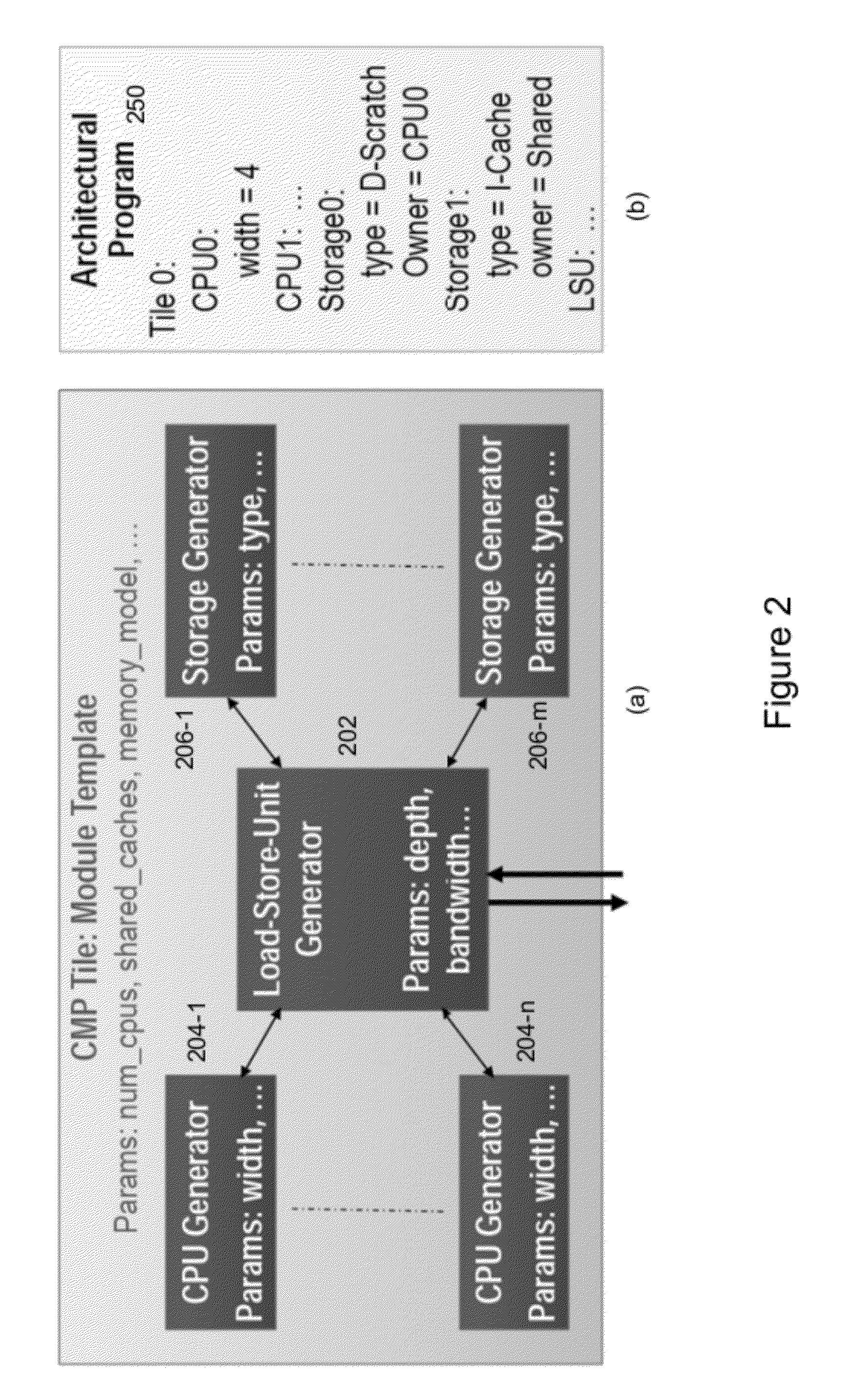
[0004]An embodiment of the present invention harnesses the ideas of reconfigurable designs to build a design framework that can generate semi-custom chips. A Chip Generator according to an embodiment of the present invention is disclosed that codifies the designer knowledge and design trade-offs into a template that can be used to create many different chips. Like reconfigurable designs, these systems fix the top level system architecture, amortizing software and validation and design costs, and enabling a rich system simulation environment for application developers. Meanwhile, below the top level, the developer can “program” the individual inner components of the architecture. Unlike reconfigurable chips, a chip generator according to an embodiment of the present invention “compiles” the program to create a customized chip. This compilation process occurs at elaboration time—long before silicon is fabricated. The result is a framework that enables more customization of the generated chip at the architectural level because additional components and logic can be added if the customization process requires it. At the same time this framework does not introduce inefficiency at the circuit level because unneeded circuit overheads are not taped out.
[0006]While logic validation of a generator may at first seem like an infeasible or very expensive task, embodiments of the present invention demonstrate that this is in fact not the case. The first key insight that enables efficient validation is that only generated instances may need to be validated—not the generator. This means that the generator can be leveraged to generate many of the validation components such as drivers, monitors and assertions, alongside the design itself. The second insight is that the validation approach can be oblivious to low level customizations details, and instead thoroughly check correctness at the higher, system level. The result is that testing multiple hardware configurations does not become harder than testing one. Moreover, a chip generator may even improve validation quality and reduce validation time because, by testing multiple closely related configurations, the probability of exposing corner case bugs increases.

Problems solved by technology

Moreover, a chip generator may even improve validation quality and reduce validation time because, by testing multiple closely related configurations, the probability of exposing corner case bugs increases.

Method used


Image

  • System and Method for a Chip Generator
  • System and Method for a Chip Generator
  • System and Method for a Chip Generator

Examples


Embodiment Construction

[0021]The following description is of certain preferred embodiments presently contemplated for carrying out this invention. This description is made for the purpose of illustrating the general principles of this invention and is not meant to limit the inventive concepts claimed herein.

[0022]The present application claims priority to Provisional Application Ser. No. 61 / 444,113, entitled “System and Method for Automatic Generation of Custom and Heterogeneous Compute Platforms” and filed on Feb. 17, 2011, that is herein incorporated by reference for all purposes.

[0023]Computer System

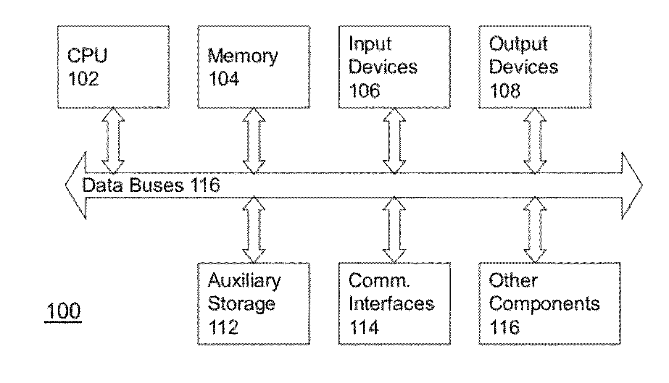
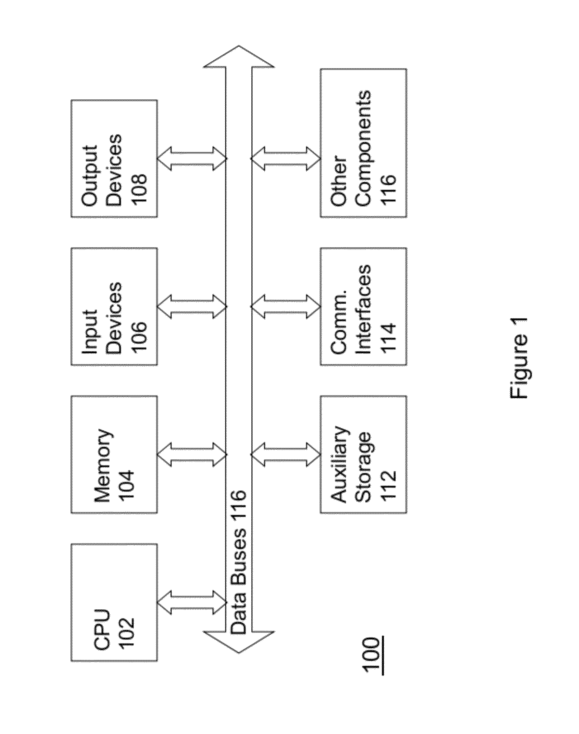
[0024]Among other things, the present invention relates to methods, techniques, and algorithms that are intended to be implemented in a digital computer system 100 such as generally shown in FIG. 1. Such a digital computer is well-known in the art and may include the following.

[0025]Computer system 100 may include at least one central processing unit 102 but may include many processors or processing cores. ...


PUM


Abstract

A chip generator according to an embodiment of the present invention codifies designer knowledge and design trade-offs into a template that can be used to create many different chips. Like reconfigurable designs, an embodiment of the present invention fixes the top level system architecture, amortizes software and validation and design costs, and enables a rich system simulation environment for application developers. Meanwhile, below the top level, the developer can “program” the individual inner components of the architecture. Unlike reconfigurable chips, a chip generator according to an embodiment of the present invention, compiles the program to create a customized chip. This compilation process occurs at elaboration time—long before silicon is fabricated. The result is a framework that enables more customization of the generated chip at the architectural level because additional components and logic can be added if the customization process requires it.

Description

FIELD OF THE INVENTION[0001]The present invention generally relates to the field of electronic design automation. More particularly, the present invention relates to a design framework that can generate designs for semi-custom chips.BACKGROUND OF THE INVENTION[0002]Recent changes in technology scaling have made power dissipation today's major performance limiter. As a result, designers struggle to meet performance requirements under stringent power budgets. At the same time, the traditional solution to power efficiency, application specific designs, has become prohibitively expensive due to increasing nonrecurring engineering (NRE) costs. Most concerning are the development costs for design, validation, and software for new systems.[0003]One direction that industry has attempted, with the goal of mitigating the rising costs of per-application designs, is to add a layer of programmability that specifies how the hardware operates. An example of this approach includes baseband processo...

Claims


Application Information

Patent Timeline
Patent Type & Authority Applications(United States)
IPC IPC(8): G06F17/50
CPCG06F17/5045G06F30/30
Inventor SHACHAM, OFERHOROWITZ, MARKRICHARDSON, STEPHEN
Owner THE BOARD OF TRUSTEES OF THE LELAND STANFORD JUNIOR UNIV
Learn More