Eureka AIR delivers breakthrough ideas for toughest innovation challenges, trusted by R&D personnel around the world.

Lithographic apparatus and device manufacturing method

a technology of lithographic apparatus and manufacturing method, which is applied in the direction of printers, seating furniture, applications, etc., can solve the problems achieve the effect of reducing the overall size of the apparatus, reducing the effect of any effect on the pattern produced on the substrate, and reducing the cost of the apparatus

Inactive Publication Date: 2005-08-18
ASML NETHERLANDS BV
View PDF22 Cites 12 Cited by
  • Summary
  • Abstract
  • Description
  • Claims
  • Application Information

AI Technical Summary

Benefits of technology

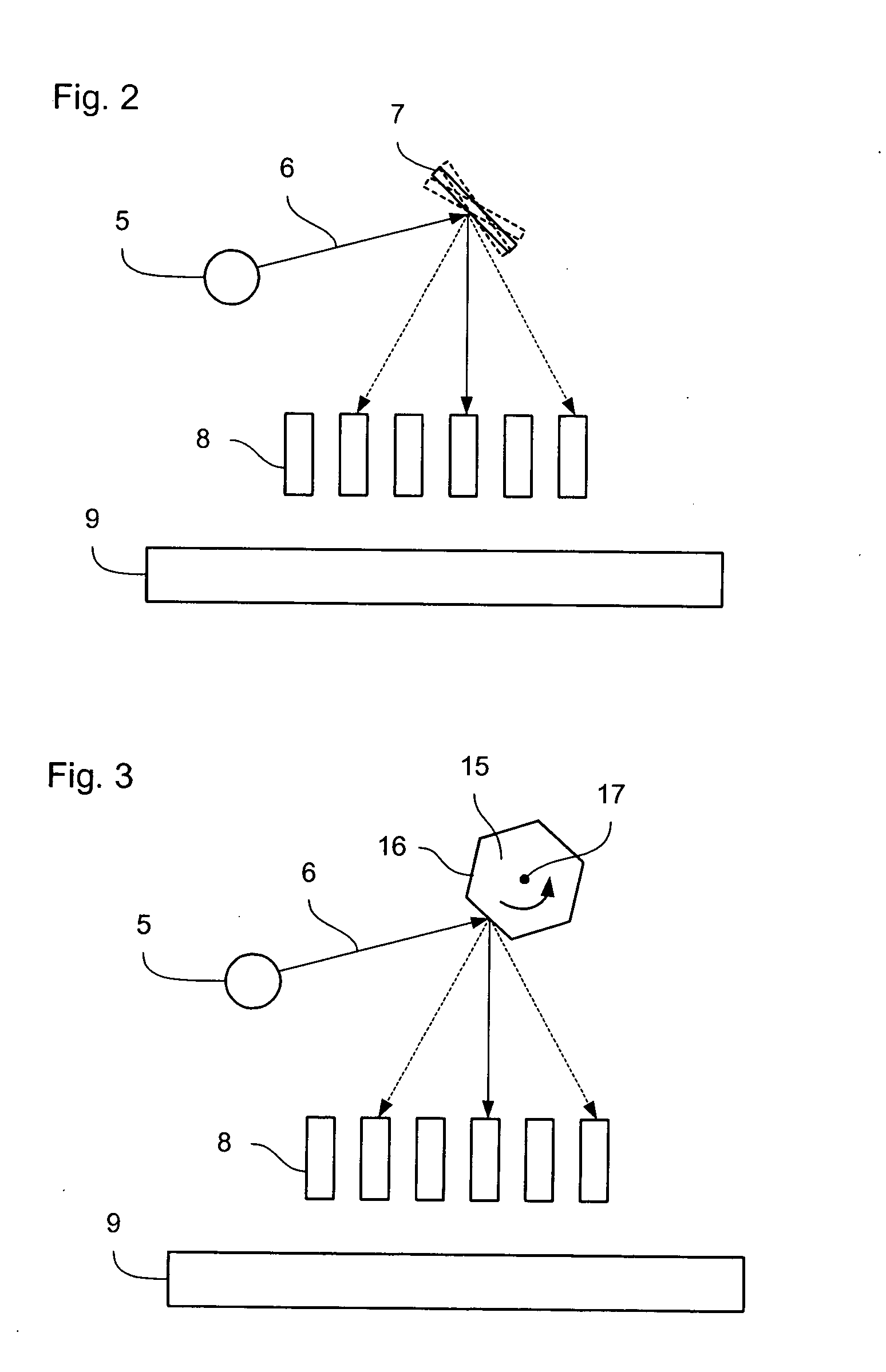
[0009] By use of such an arrangement, a single radiation source can efficiently provide radiation for a plurality of patterning means. Consequently, the apparatus cost is reduced by having a separate illumination system for each patterning means. Furthermore, use of a single illumination system reduces the overall size of the apparatus. As a further advantage, by using a single illumination system, the variation in intensity provided to each patterning means may be less than if each patterning means was supplied by an independent illumination system. Consequently, the radiation dose provided by different patterning means will be more consistent, reducing any effects on the pattern produced on the substrate caused by transitions between different regions that have been illuminated at slightly different intensities.
[0010] Such an arrangement may, of course, be scaled up to distribute the radiation from one illumination system to three or more patterning means. In a preferred arrangement of each radiation distribution channel directs radiation to a single one of the patterning means. This approach has the advantage of each patterned beam having the full intensity radiation of the illumination system, reducing the time required to provide a given radiation dose.
[0011] Alternatively, however, at least one of the radiation distribution channels may include a beam splitter for dividing the radiation directed into that radiation distribution channel and distributing it to two or more patterning means. This arrangement allows a greater number of patterning means to be illuminated by a single illumination system.
[0023] In any one of the arrangements discussed above, the patterning means may preferably be an array of individually controllable elements. Accordingly, the array of individually controllable elements may be set to impart to the associated beam of radiation any desired pattern in its cross-section. Therefore, for example, in apparatus according to the first aspect of the invention, the use of the radiation distribution device has the advantage that while the pattern on one array is being updated (i.e., set to a new pattern), the pattern set on another array may pattern a beam of radiation which exposes the pattern on the substrate.
[0028] This arrangement allows for a beam of greater radiation intensity to be generated by the illumination system. In addition, radiation sources vary in intensity during operation but the variation of the intensity of the sum of the beams of radiation generated by independent radiation sources is lower. The beam combiner may include a radiation beam integrator in order to ensure that, even if the beams of radiation generated by each radiation source have different intensities, the intensity distribution the cross-section of the combined beam of radiation from the illumination system is substantially uniform.

Problems solved by technology

Furthermore, use of a single illumination system reduces the overall size of the apparatus.

Method used


Image

  • Lithographic apparatus and device manufacturing method
  • Lithographic apparatus and device manufacturing method
  • Lithographic apparatus and device manufacturing method

Examples


second embodiment

[0089]FIG. 4 is an illustration of a radiation distribution element 20 used in a further variant of the invention. In this case, the reflective surfaces 22, 23, 24, 25, 26, 27 are not arranged to form a regular polygon. Instead, as schematically represented, each reflector is arranged at a different angle, compared to the other reflective surfaces, to the position that the reflective surface would have been at were they to form a regular polygon (such a regular polygon 21 is shown in broken lines for comparison).

[0090] For clarity, the reflective surfaces have not been shown joined to one another. However, it will be appreciated, that in practice, they may be so joined, for example if the radiation distribution element 20 were made from a solid piece of material. With such an arrangement, the radiation distribution element 20 can be arranged to rotate at the same speed as (or an integer multiple of) the pulse rate of the illumination system 5. In particular, although between each pu...

third embodiment

[0095]FIG. 5 represents the present invention. Provided is a radiation distribution system that can simultaneously provide radiation to two or more radiation distribution channels (or light engines 8). In particular, where a pulsed illumination system is being used, the radiation distribution element 30 can divide each pulse between the radiation distribution channels. Furthermore, the arrangement shown can be used as a beam divider within one of the radiation distribution channels, as described above.

[0096] As shown in FIG. 5, a radiation distribution element 30 is comprised of a plurality of sections 31, 32, 33, 34, 35, 36, each associated with a radiation distribution channel or light engine 8. Each section is comprised of a material which is substantially transmissive to the radiation used and, may be formed from rods of glass or quartz, in particular. It will be appreciated, however, that the cross-sectional shape of these sections may be any convenient shape.

[0097] The first ...


PUM


Abstract

Provided is a radiation distribution system for distributing the radiation from an illumination system to two or more patterning means, each for patterning beams of radiation, which are subsequently projected onto a substrate.

Description

BACKGROUND OF THE INVENTION [0001] 1. Field of the Invention [0002] The present invention relates to a lithographic apparatus and a device manufacturing method. [0003] 2. Related Art [0004] A lithographic apparatus is a machine that applies a desired pattern onto a target portion of a substrate. A lithographic apparatus can be used, for example, in the manufacture of integrated circuits (ICs), flat panel displays and other devices involving fine structures. In a conventional lithographic apparatus, a patterning means, which is alternatively referred to as a mask or a reticle, may be used to generate a circuit pattern corresponding to an individual layer of the IC (or other device, such as a flat panel display), and this pattern can be imaged onto a target portion (e.g., comprising part of, one or several dies) on a substrate (e.g., a silicon wafer or glass plate) that has a layer of radiation-sensitive material (resist). Instead of a mask, the patterning means may comprise an array ...

Claims


Application Information

Patent Timeline
IPC IPC(8): G03F7/20H01L21/027
CPCG03F7/70208G03F7/70291G03F7/70283G03F7/70275A47G9/1027A47C4/54
Inventor GUI, CHENG-QUNBLEEKER, ARNO JANDE JAGER, PIETER WILLEM HERMANSYTSMA, JOOST
Owner ASML NETHERLANDS BV
Why Eureka
Eureka Blog
Learn More