
Spindle structure of a machine tool

a machine tool and spindle technology, applied in the direction of attachment devices, manufacturing tools, transportation and packaging, etc., can solve the problems of high transfer torque produced between the spindle and the tool holder, and achieve the effect of stable shackling, high transfer torque and stable holding

Inactive Publication Date: 2005-08-11
FANUC LTD
View PDF11 Cites 8 Cited by
  • Summary
  • Abstract
  • Description
  • Claims
  • Application Information

AI Technical Summary

Benefits of technology

[0016] According to the present invention, a tool holder and a spindle can be stably shackled by means of the tapered surfaces and the end surfaces without need for the provision of a movable part or the implementation of a rigid processing accuracy and, in addition, a high transfer torque can be produced, and the tool can be held stably.
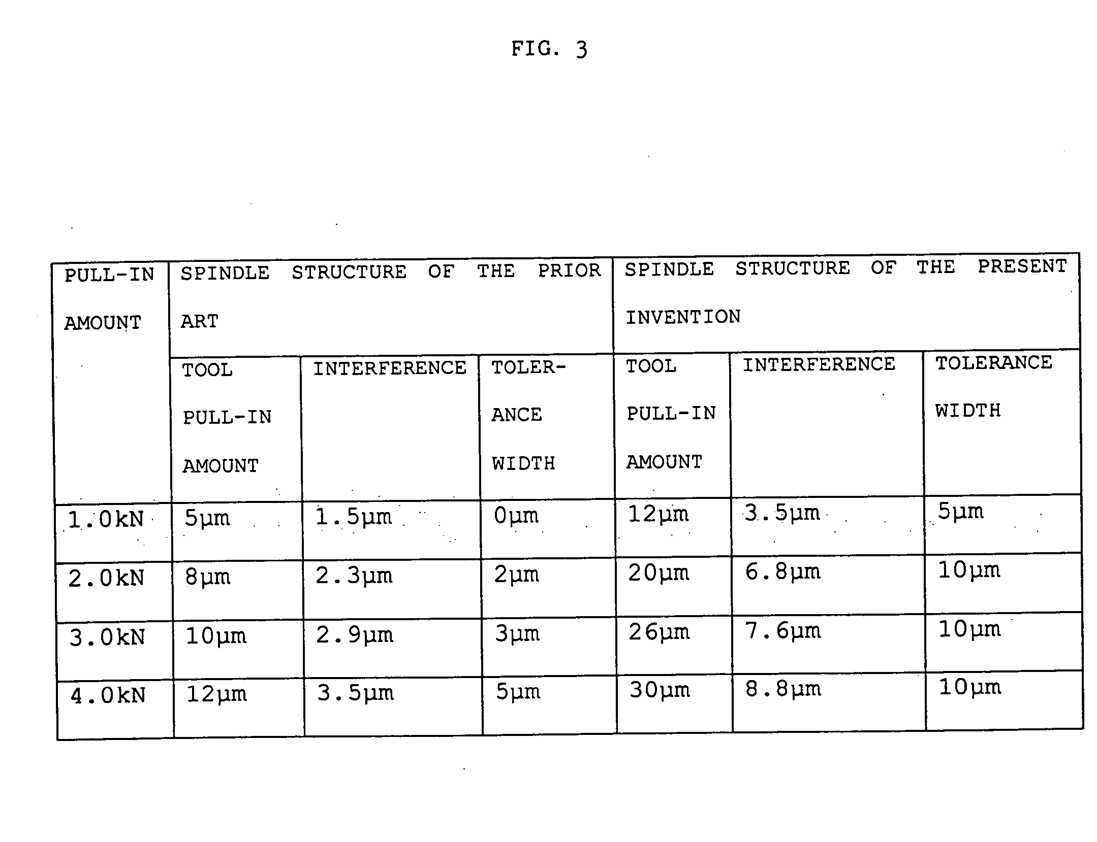
[0017] According to the spindle structure of a machine tool of the present invention, by localizing the contact between the tapered surfaces to the toroidal cone section, the sections of contact can be easily elastically deformed so that, after the tapered surfaces of the tool holder and spindle are brought into contact, the tool holder can be fully pulled in whereby, accordingly, a stable dual-surface shackled state is able to be produced, the range of the permissible error of the positional relationship between the tapered surface and the end surface of the spindle can be increased and, in addition, because of the lowering of the demanded processing accuracy, the manufacturing costs can be suppressed.
[0018] In addition, by virtue of the fact that the interference between the tool holder and the spindle can be set larger so as to increase the surface pressure generated in the tapered surfaces and, in addition, there is no floating state generated due to the interposing of an oil film because the contact surface area between the tapered surfaces is narrowed, a high transfer torque can be produced between the spindle and the tool holder.
[0019] Furthermore, as a result of the increased interference established in advance, loss of interference is eliminated and the tool can continue to be held in a stable state even if the recessed cone part of the spindle expands during high-speed rotation of the spindle.

Problems solved by technology

In addition, by virtue of the fact that the interference between the tool holder and the spindle can be set larger so as to increase the surface pressure generated in the tapered surfaces and, in addition, there is no floating state generated due to the interposing of an oil film because the contact surface area between the tapered surfaces is narrowed, a high transfer torque can be produced between the spindle and the tool holder.

Method used


Image

  • Spindle structure of a machine tool
  • Spindle structure of a machine tool
  • Spindle structure of a machine tool

Examples


first embodiment

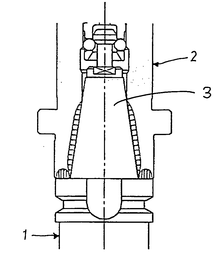
[0029] A description of the spindle structure of a machine tool according to the present invention is given below with reference to FIG. 1.

[0030] In the spindle structure shown in FIG. 1, a tool is connected to the spindle 2 and the work of the spindle 2 is transferred to the tool by the attachment to the spindle 2 of a tool holder 1 on which a tool (not shown) such as a cutting tool is mounted.

[0031] A projecting cone part 3 is integrally provided in the center part of the end surface la of the tool holder 1 in such a way that the axis thereof aligns with the axis of the tool holder 1. A pull stud 4 is provided upright in the apex part of the projecting cone part 3 along the axial direction of the projecting cone part 3.

[0032] A recessed cone part 5 is formed in the center part of the end surface 2a of the spindle 2 in such a way that the axis thereof aligns with the axis of the spindle 2. A draw bar 6 which detachably grasps the pull stud 4 of the tool holder 1 is arranged in th...

second embodiment

[0044] By way of example, in the embodiment shown in FIG. 5 (the spindle structure of the machine tool according to the present invention), the toroidal cone section 7 is formed in the recessed cone part 5 at an upper portion thereof in the axial direction of the spindle.

third embodiment

[0045] In the embodiment shown in FIG. 6 (the spindle structure of the machine tool according to the present invention), the toroidal cone section 7 is formed in the recessed cone part 5 at a lower end portion thereof in the axial direction of the spindle.


PUM

PropertyMeasurementUnit
inner diameteraaaaaaaaaa
pull-in forceaaaaaaaaaa
tolerance widthaaaaaaaaaa

Abstract

A tool holder is attached to a spindle by the contacting of the projecting cone part and end surface of the tool holder with the recessed cone part and end surface of the spindle respectively. A toroidal cone section is provided on the inner side surface of the recessed cone part of the spindle so as to protrude inward. The diameter of the toroidal cone section is formed smaller than the diameter of the section of the projecting cone part of the tool holder that abuts the toroidal cone section.

Description

BACKGROUND OF THE INVENTION [0001] 1. Field of the Invention [0002] The present invention relates to a spindle structure of a machine tool in which a tool holder is supported by, and removable from, the spindle. [0003] 2. Description of the Related Art [0004] In the connecting of a tool holder on which a tool such as a cutting tool is mounted to the spindle of a machine tool, first, a projecting cone part provided in the end surface of the tool holder is fitted into a recessed cone part formed in the tip-end part of the spindle. Thereafter, using a drawbar arranged in the spindle side, a pull stud provided in the apex part of the projecting cone part (tapered surface) of the tool holder is drawn up so as to bring the recessed cone part of the spindle into contact with the projecting cone part (tapered surface) of the tool holder of the tool holder. [0005] However, there are drawbacks inherent to structures in which the tool holder and the spindle are coupled by contact between the t...

Claims


Application Information

Patent Timeline
Patent Type & Authority Applications(United States)
IPC IPC(8): B23B31/117B23B19/02B23B31/00B23B31/26
CPCB23B31/006B23B31/261B23B2231/0204Y10T409/309408Y10T408/95Y10T409/309464B23B2231/0288
Inventor WATANABE, NORIOFUJIMOTO, AKIHIKOMUBOTA, MASAHIRO
Owner FANUC LTD
Learn More