
Active noise control system in unrestricted space

a noise control and unrestricted space technology, applied in the field of noise control systems, can solve the problems of slow adaptation to primary source changes, inability to rapidly change the noise of the primary source, and conventional adaptive cancellation systems using traditional transverse finite impulse response (fir) filters, which are well known in the prior art, and can not be used to cancel rapid change of nois

Inactive Publication Date: 2005-08-11
WRIGHT COMPANY
View PDF6 Cites 37 Cited by
  • Summary
  • Abstract
  • Description
  • Claims
  • Application Information

AI Technical Summary

Benefits of technology

[0006] According to a first aspect of the present invention there is provided a noise control system as set out in claim 1.

Problems solved by technology

Conventional adaptive cancellation systems using traditional transverse finite impulse response (FIR) filters, together with least mean square (LMS) adaptive algorithms, well known in the prior art, are slow to adapt to primary source changes.
This makes them inappropriate for cancelling rapidly changing noise, including unpredictable noise such as speech and music.
Secondly, the cancelling structures require considerable computational processing effort to adapt to primary source and plant changes, particularly for multi-channel systems.
But for source frequencies varying in time the smaller amplitudes will not have time to catch up (adapt completely), producing slow adaptation and signal distortion.
Further disadvantages of the conventional transverse FIR adaptive systems are (i) basic instability, where the error sensor is permanently required and functioning to maintain stability (ii) deteriorated cancellation away from the error sensor and (iii) susceptibility to environmental changes, through a large controlling propagation distance.

Method used


Image

  • Active noise control system in unrestricted space
  • Active noise control system in unrestricted space
  • Active noise control system in unrestricted space

Examples


Embodiment Construction

[0014] In the figures, like reference numerals indicate like parts and multiple like elements are denoted using lower case letters as sub-reference numerals.

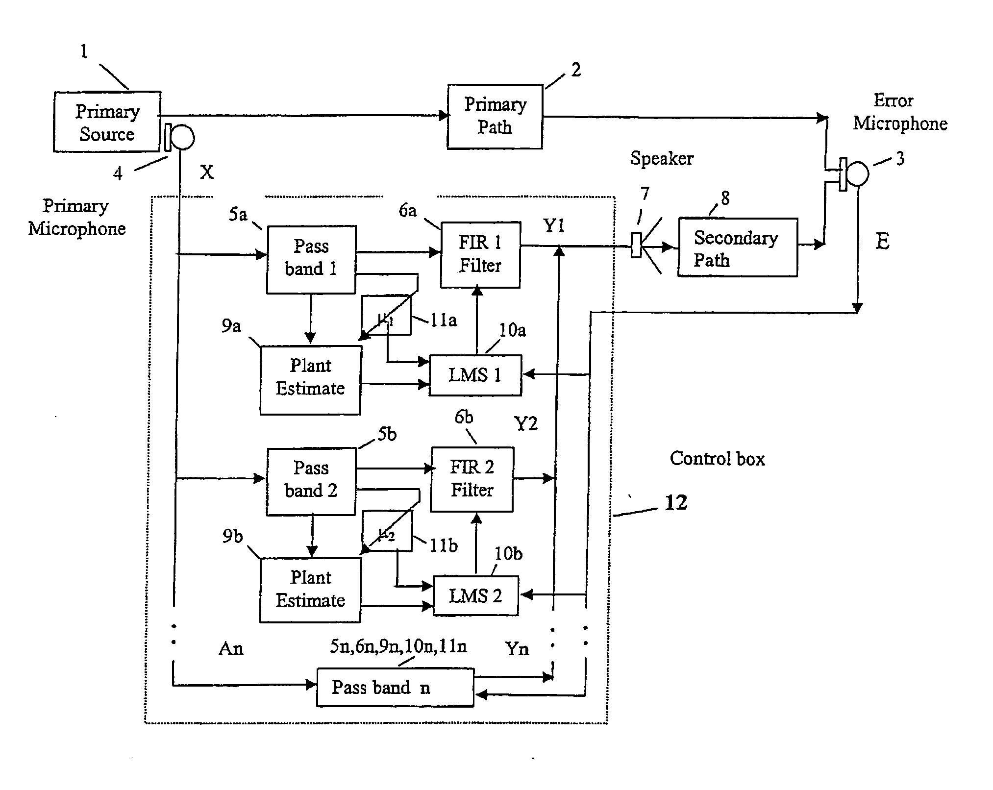
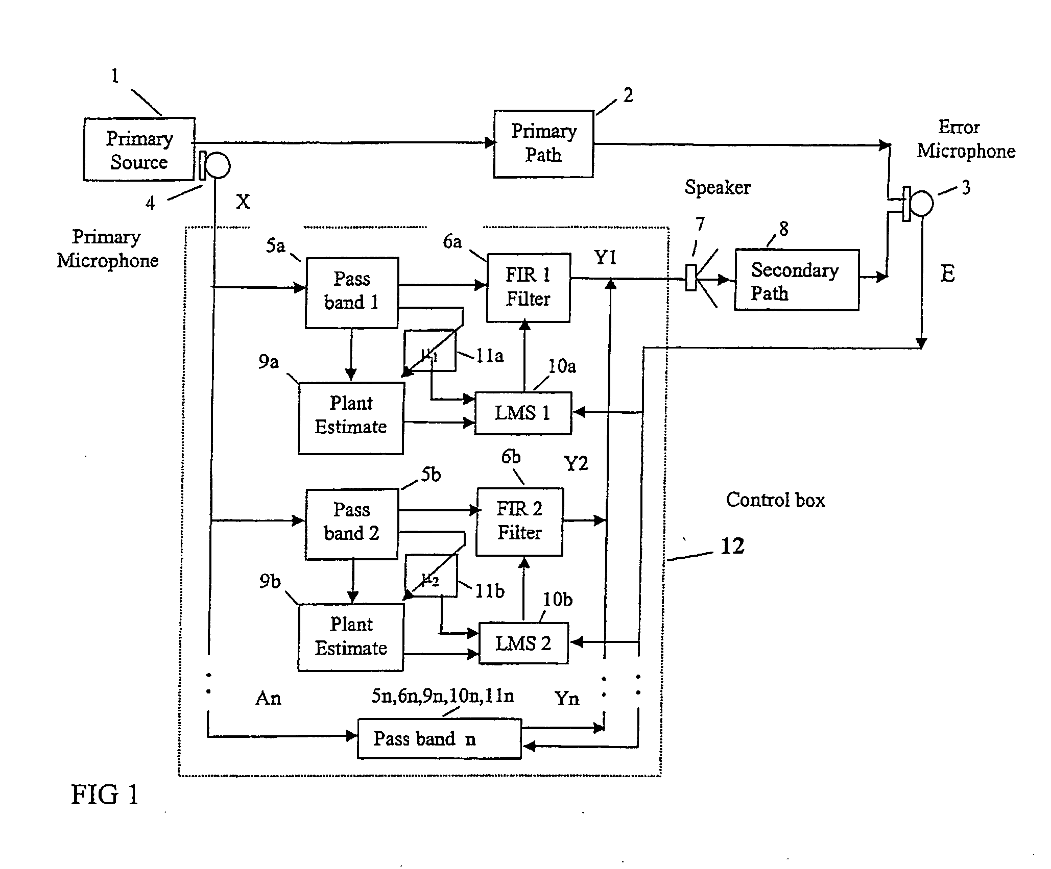
[0015] Referring firstly to FIG. 1, there is shown a multi-passband, variable μ, fixed β method to increase the adaptive speed of transverse FIR filters to primary source changes. The approach is to divide the source spectrum bandwidth into frequency pass-bands, where each passband has a separate FIR filter with its own μ made inversely proportional to A2 in each passband, tending to maintain a constant β and therefore adaptive speed, irrespective of the spectrum amplitude. Thus a faster and similar response of the cancellation sound to the unwanted noise, will be more nearly obtained as the number of passbands increase for a given total spectrum bandwidth.

[0016]FIG. 1 shows a primary noise source 1 which produces a primary noise to be cancelled. This noise is shown to propagate along a primary path 2. There is further shown a...


PUM


Abstract

The adaptive speed to changes in a primary source noise is increased through a noise detecting means feeding parallel multi-passband means and multi-transverse adaptive filter means, where each adaptive filter has its own individual adaptive step size means adjusted automatically according to the signal strength at each passband output. The output from each of the multi-adaptive filter means drives a secondary canceling source generating means where each multi-adaptive filter means is automatically adjusted to produce minimum sound in its passband at an error detecting means. Alternatively, the output from the noise detecting means is negated through a negation means, passed through a plant neutralization inverse means and an inverse delay means before driving the secondary source generating means. The secondary source output is aligned and match in amplitude to that of the primary sources, through a delay buffer means and an amplitude regulator means, which are adjusted successively until the output at the error detector means is a minimum.

Description

FIELD OF INVENTION [0001] The present invention relates to a noise control system, which is preferably an active noise control system, and a method for controlling noise, particularly but not exclusively in large unrestricted spaces. BACKGROUND OF INVENTION [0002] Conventional adaptive cancellation systems using traditional transverse finite impulse response (FIR) filters, together with least mean square (LMS) adaptive algorithms, well known in the prior art, are slow to adapt to primary source changes. This makes them inappropriate for cancelling rapidly changing noise, including unpredictable noise such as speech and music. Secondly, the cancelling structures require considerable computational processing effort to adapt to primary source and plant changes, particularly for multi-channel systems. [0003] A general structure for such a cancellation system is shown in the applicant's international application having publication no. WO 01 / 63594. Here a primary source to be cancelled, a...

Claims


Application Information

Patent Timeline
Patent Type & Authority Applications(United States)
IPC IPC(8): G10K11/178
CPCG10K11/1782G10K2210/3042G10K2210/3027G10K11/17855G10K11/17823G10K11/17881G10K11/17854G10K11/17857
Inventor WRIGHT, SELWYN EDGARVUKSANOVIC, BRANISLAVATMOKO, HIDAJAT
Owner WRIGHT COMPANY
Learn More