
Superconducting magnet system with drift compensation

a superconducting magnet and drift compensation technology, applied in the field of active shielding, superconducting magnet systems, can solve the problem of negligible heat input in cryostats, and achieve the effect of keeping the temperature of the cryostats at a minimum of 106

Active Publication Date: 2005-08-11
BRUKER BIOSPIN
View PDF8 Cites 7 Cited by
  • Summary
  • Abstract
  • Description
  • Claims
  • Application Information

AI Technical Summary

Benefits of technology

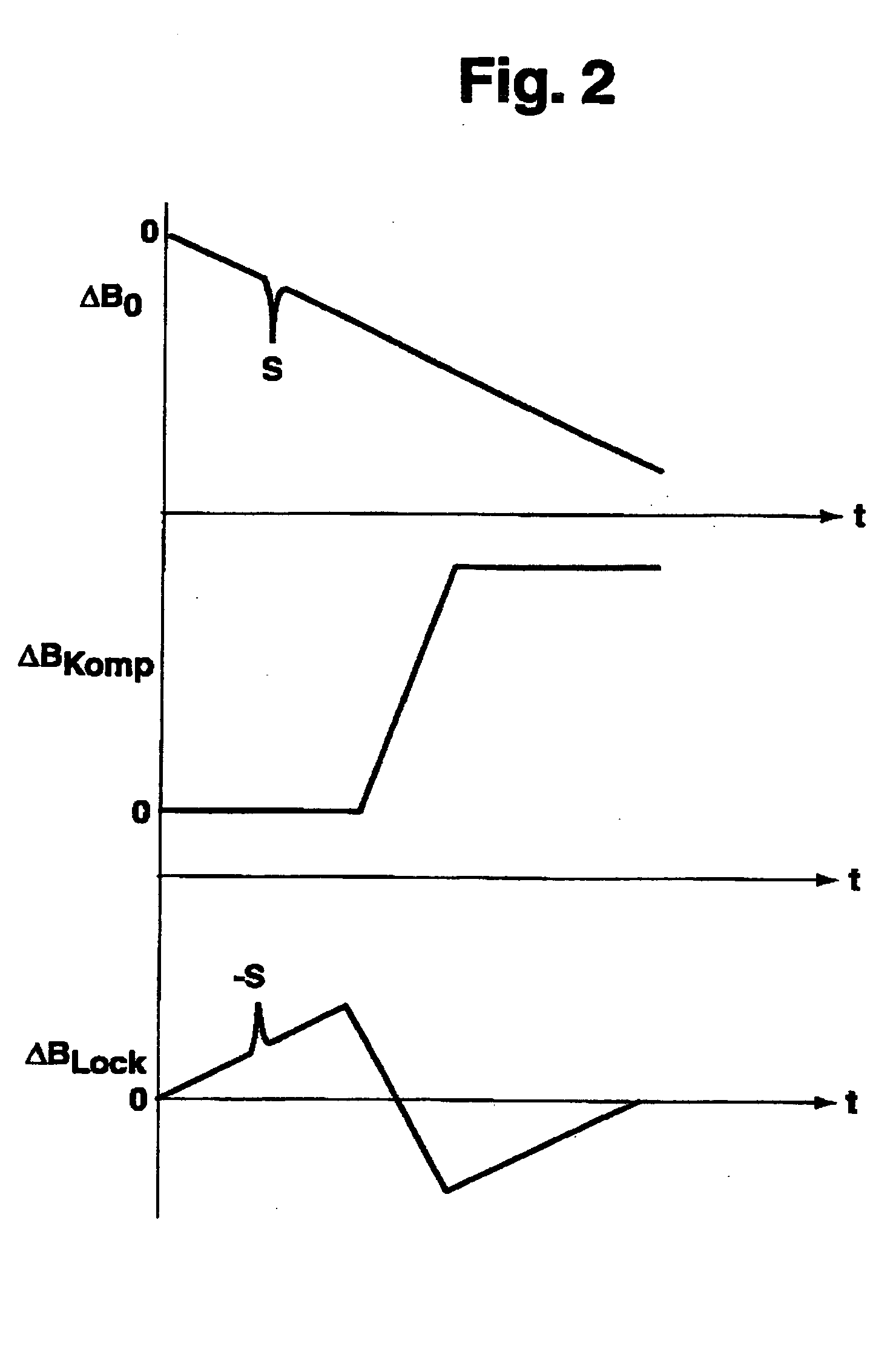
[0021] Later rough compensation adjustment in long time interval stages may thereby be sufficient. The drift compensation coil may also be temporarily superconductingly short-circuited. One must thereby take into consideration the fact that it then no longer compensates for a continuous drift. In this case, fine adjustment and temporary drift compensation is provided by the (resistive) lock system. Due to the fact that the contribution of the compensation field to the overall field is very small (as small as approximately 10−5), the noise which is thereby inevitably introduced into the high-resolution spectrometer can be tolerated, since it can be easily kept below 10−6. The inductive coupling between the compensation coil and the superconducting circuit of the main coil is eliminated and inductive coupling to the shim system should either be eliminated in the arrangement or be taken into consideration in the design.

Problems solved by technology

Moreover, due to the use of a superconductor, in particular, a relatively thin wire, which is operated at low current and high charging voltage of the compensation coil(s), the heat input in the cryostat is negligibly small.

Method used


Image

  • Superconducting magnet system with drift compensation
  • Superconducting magnet system with drift compensation
  • Superconducting magnet system with drift compensation

Examples


Embodiment Construction

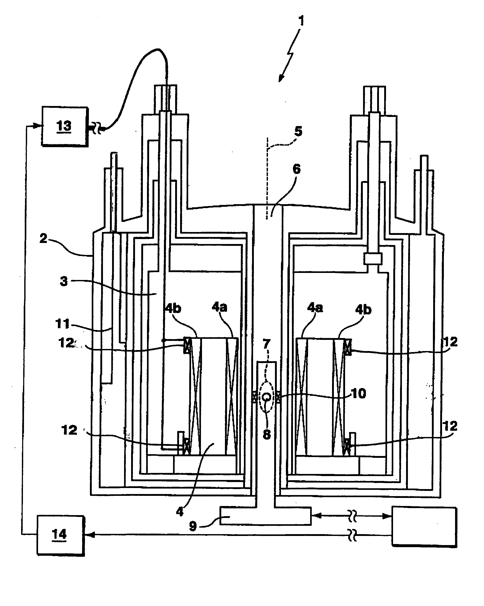
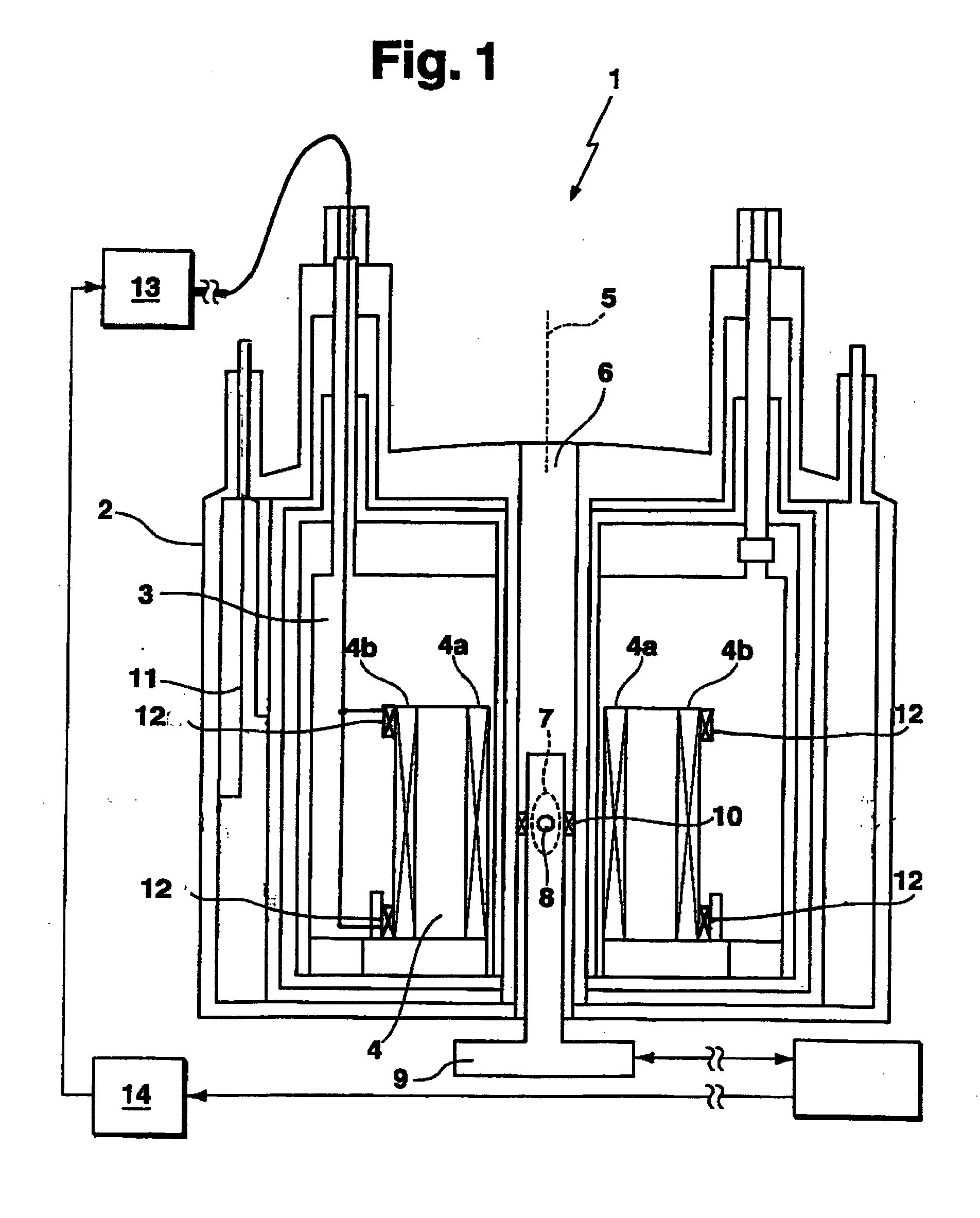
[0036]FIG. 1 schematically shows, in detail, a section through the substantially rotationally-cylindrical cryostat of the superconducting magnet system 1 e.g. of a high-resolution NMR apparatus. The magnet coil 4 which is superconductingly short-circuited during operation is disposed in a helium tank 3 of the cryostat 2 and is actively shielded, e.g. consists of two opposite partial coils 4a (main coil) and 4b (shielding coil). The cryostat 2 has a room temperature bore 6 along its cylindrical axis 5, within which a sample 8 is disposed in a measuring region 7 at the center of the magnet coil 4, the sample being surrounded by an RF transmitter and receiver coil arrangement 9 (probe head).

[0037] A so-called lock coil 10 is also located inside the room temperature bore 6, optionally integrated in the probe head 9, for fine correction of the magnetic field in the measuring region. This lock coil 10 is not or only slightly coupled to the magnet coil 4. The correction current through th...


PUM


Abstract

The system describes a means and a method for stabilizing the magnetic field generated in the measuring volume of a high-resolution magnetic resonance spectrometer having an actively shielded magnet coil (4) which is located in a cryostat (2) and which is superconductingly short-circuited. The system comprises a compensation coil (12) which is decoupled from the magnet coil (4), and is disposed on the shielding coil (4b) of the magnet coil (4).

Description

[0001] This application claims Paris Convention priority of DE 10 2004 005 744.3 filed Feb. 5, 2004 the complete disclosure of which is hereby incorporated by reference. BACKGROUND OF THE INVENTION [0002] The invention concerns an actively shielded, superconducting magnet system, in particular, for a high-resolution magnetic resonance spectrometer, comprising a substantially cylindrical cryostat with an axial room temperature bore for receiving a sample, a radio-frequency transmitting and detecting system, and a magnet coil which is superconductingly short-circuited during operation and comprises a main coil and a shielding coil which radially surrounds the main coil, wherein the magnet coil is disposed at a low temperature in a region within the cryostat to surround the sample in the room temperature bore and generate a homogeneous, temporally stable magnetic field at the sample location during operation, the magnetic field meeting requirements for obtaining a high-resolution magne...

Claims


Application Information

Patent Timeline
IPC IPC(8): G01R33/3815G01R33/389G01R33/421
CPCG01R33/3815G01R33/421G01R33/389G01R33/3875
Inventor KASTEN, ARNEWESTPHAL, MICHAEL
Owner BRUKER BIOSPIN
Learn More