
Wire for removing foreign matter in blood vessel and medical device using the wire

a technology for blood vessels and foreign matter, which is applied in the field of wires for removing foreign matter in blood vessels and medical devices using wires, can solve the problems of inability to reliably catch foreign matter in some cases, increase the death or aftereffect of cerebral apoplexy, and urgent establishment of curing methods

Inactive Publication Date: 2005-08-04
TERUMO KK
View PDF14 Cites 139 Cited by
  • Summary
  • Abstract
  • Description
  • Claims
  • Application Information

AI Technical Summary

Benefits of technology

The present invention provides a wire for removing foreign matter in a blood vessel. The wire has a flexible elongated wire body with two movable holding portions at the front end of the wire body. The holding portions can be moved relative to each other to hold the foreign matter in the blood vessel. The wire can be used in a medical device or catheter to catch and remove foreign matter in the blood vessel. The position of holding the foreign matter can be changed according to its size, and the wire can be easily recognized under radioscopy. The technical effects of the invention are that it provides a reliable and efficient way to catch and remove foreign matter in the blood vessel, regardless of its size.

Problems solved by technology

In particular, the death or aftereffect due to cerebral apoplexy has increased and the establishment of a curing method therefor has become urgent.
However, the conventional wire has a problem such that the foreign matter cannot be reliably caught in some cases as depending upon the size of the foreign matter.
For example, when the size of the foreign matter is larger than that of the foreign matter catching portion, there is a case that the foreign matter may fall from the foreign matter catching portion during the catching operation.
In such a case, an operation for replacing the smaller wire by a larger wire according to the size of the foreign matter, for example, may be required to cause a troublesome manipulation.

Method used


Image

  • Wire for removing foreign matter in blood vessel and medical device using the wire
  • Wire for removing foreign matter in blood vessel and medical device using the wire
  • Wire for removing foreign matter in blood vessel and medical device using the wire

Examples


first preferred embodiment

(First Preferred Embodiment)

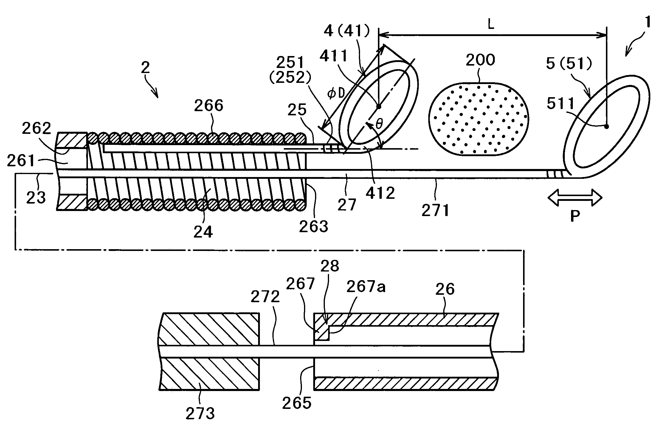
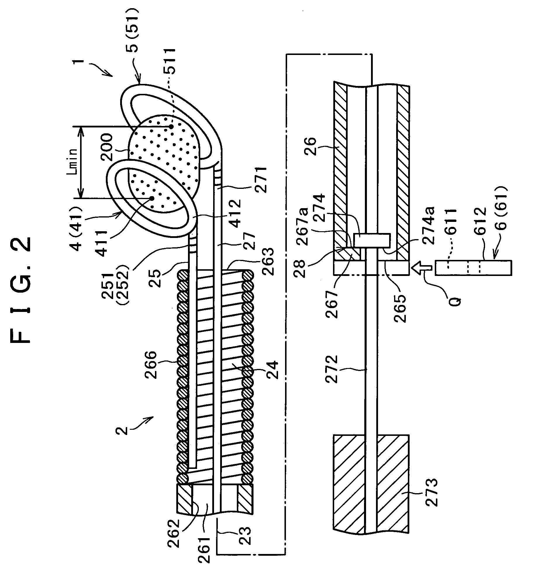
[0024]FIG. 1 is a longitudinal sectional view showing a first preferred embodiment of the wire for removing foreign matter in a blood vessel according to the present invention. FIG. 2 is a longitudinal sectional view showing a condition where the foreign matter is held by the wire shown in FIG. 1. FIGS. 3A and 3B are a plan view and a side view of retaining means included in the wire shown in FIG. 1, respectively. FIGS. 4 to 8 are longitudinal sectional views for sequentially illustrating the steps of a using method for the wire shown in FIG. 1.

[0025] In the following description, the terms of “base end (proximal end)” and “front end (distal end)” mean the left side and the right side as viewed in FIGS. 1 and 2, respectively, and mean the right side and the left side as viewed in FIGS. 4 to 8, respectively.

[0026] Referring to FIG. 1, reference numeral 1 generally denotes the wire according to the first preferred embodiment. The wire 1 is designed to san...

second preferred embodiment

(Second Preferred Embodiment)

[0097]FIG. 9 is a longitudinal sectional view showing a second preferred embodiment of the wire for removing foreign matter in a blood vessel according to the present invention. FIG. 10 is a longitudinal sectional view showing a condition where the foreign matter is held by the wire shown in FIG. 9.

[0098] While the second preferred embodiment will now be described with reference to FIGS. 9 and 10, only a difference between the first preferred embodiment and the second preferred embodiment will be focused and the description of similar points will be omitted herein.

[0099] In the following description, the terms of “base end” and “front end” mean the left side and the right side as viewed in FIGS. 9 and 10, respectively.

[0100] The second preferred embodiment is similar to the first preferred embodiment except the configuration of the first and second holding portions.

[0101] As shown in FIG. 9 (also shown in FIG. 10), the wire 1 according to the second ...

third preferred embodiment

(Third Preferred Embodiment)

[0111]FIG. 11 is a longitudinal sectional view showing a third preferred embodiment of the wire for removing foreign matter in a blood vessel according to the present invention. FIG. 12 is a longitudinal sectional view showing a condition where the foreign matter is held by the wire shown in FIG. 11.

[0112] While the third preferred embodiment will now be described with reference to FIGS. 11 and 12, only a difference between the first preferred embodiment and the third preferred embodiment will be focused and the description of similar points will be omitted herein.

[0113] In the following description, the terms of “base end” and “front end” mean the left side and the right side as viewed in FIGS. 11 and 12, respectively.

[0114] The third preferred embodiment is similar to the first preferred embodiment except the configuration of the second holding portion.

[0115] As shown in FIG. 11 (also shown in FIG. 12), the wire 1 according to the third preferred em...


PUM


Abstract

Disclosed herein is a wire for removing foreign matter such as an embolus in a blood vessel. The wire includes a flexible elongated wire body and first and second holding portions provided at the front end of the wire body in spaced relationship with each other. The first and second holding portions are movable relative to each other in a longitudinal direction of the wire body. In operation, the first and second holding portions are moved relative to each other to reduce the distance between the first and second holding portions, thereby holding the foreign matter therebetween. Accordingly, the foreign matter in the blood vessel can be caught and removed reliably irrespective of the size of the foreign matter.

Description

[0001] This application claims priority on Japanese patent application No. 2003-402117, the entire contents of which are hereby incorporated by reference. BACKGROUND OF THE INVENTION [0002] The present invention relates to a wire for removing foreign matter such as an embolus in a blood vessel and a medical device using the wire. [0003] According to the dynamic statistics of population by the Ministry of Health, Labour and Welfare, the causes of death of the Japanese are cancer as the first rank, heart disease as the second rank, and cerebral apoplexy as the third rank. In particular, the death or aftereffect due to cerebral apoplexy has increased and the establishment of a curing method therefor has become urgent. [0004] In recent years, in the treatment for cerebral apoplexy, thrombolytic therapy using a thrombolytic agent for the treatment for acute-phase cerebral infarction has been developed and a curing effect has been exhibited. However, the limit of this effect has been poin...

Claims


Application Information

Patent Timeline
Patent Type & Authority Applications(United States)
IPC IPC(8): A61B17/00A61B17/22
CPCA61B17/22A61B2017/2212A61B2017/00867A61B17/221
Inventor KANAMARU, TAKESHI
Owner TERUMO KK
Learn More