Multi-layered flexible tube

Inactive Publication Date: 2005-08-04
FLUID ROUTING SOLUTIONS
View PDF29 Cites 37 Cited by
  • Summary
  • Abstract
  • Description
  • Claims
  • Application Information

AI Technical Summary

Benefits of technology

[0004] In accordance with one aspect of the present invention, a multi-layered coolant tube having improved hoop strength when compared to previous hoses and which still meets the current requirements of the automotive industry is constructed from at least two, preferably three separate layers of a polymeric material. The layers of polymeric material comprise a first polymeric tubular structure, a second foamed, reinforcement-containing polymeric material adjacent the outer surface of the first polymeric tubular structure and, preferably a third polymeric cover adjacent the outer surface of the reinforcement-containing polymeric layer. Any suitable polymeric material such as thermoplastic polymers, thermoplastic vulcanizates, and elastomeric polymers may be used in forming any or all of the various layers of the multi-tubular hose.
[0008] Each of the first tubular structure, the intermediate reinforcement layer and the cover layer may be formed from the same or from different polymeric materials. The intermediate polymeric material is generally distinguished from the first and third polymeric layers, in that the intermediate polymeric material is a foamed material containing a plurality of reinforcing elements in the form of short or long fibers or elements. The intermediate reinforcement layer preferably contains an adhesive material such as modified polypropylene, e.g., maleated polypropylene available from Atofina, in a sufficient amount to enhance the adherence o the intermediate polymeric material to the reinforcement fibers.
[0010] In accordance with another aspect of the invention, a method for manufacturing the coolant hose of the present invention comprises extruding the polymeric materials to form the multi-layered coolant hose. The various layers of polymeric material may be extruded simultaneously through the same extruder head or sequentially through different extruder heads. Preferably, the various layers are extruded at the same time in the same head. It has been found that, by extruding the various layers through a single extruder head without the need for additional stations, the production rate of the coolant hose is remarkably increased and the length of the extrusion runs become virtually unlimited, thereby significantly decreasing the complexity and the production costs of the hose.

Problems solved by technology

The application of the reinforcement greatly increases the complexity of the manufacture process by requiring a separate manufacturing step wherein the inner tubular structure of the hose is cooled in order to apply the reinforcing material and then heated up again before extruding any subsequent layers, resulting in decreased production rates.
Furthermore, specialized machinery, which takes up a considerable amount of critical space, is required to apply the reinforcement.

Method used


Image

  • Multi-layered flexible tube
  • Multi-layered flexible tube

Examples


Embodiment Construction

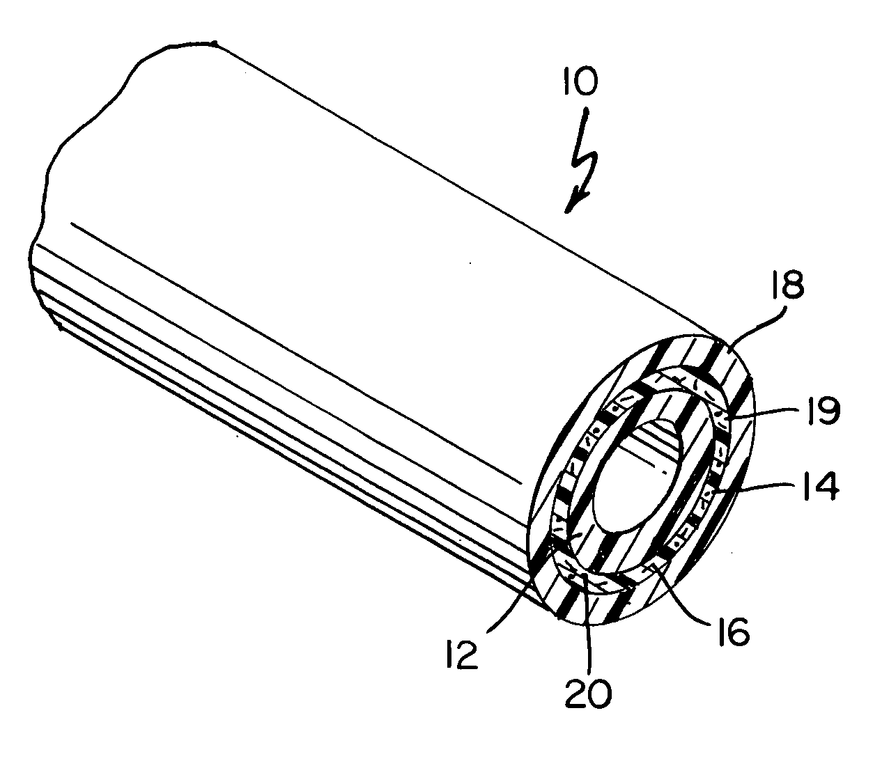
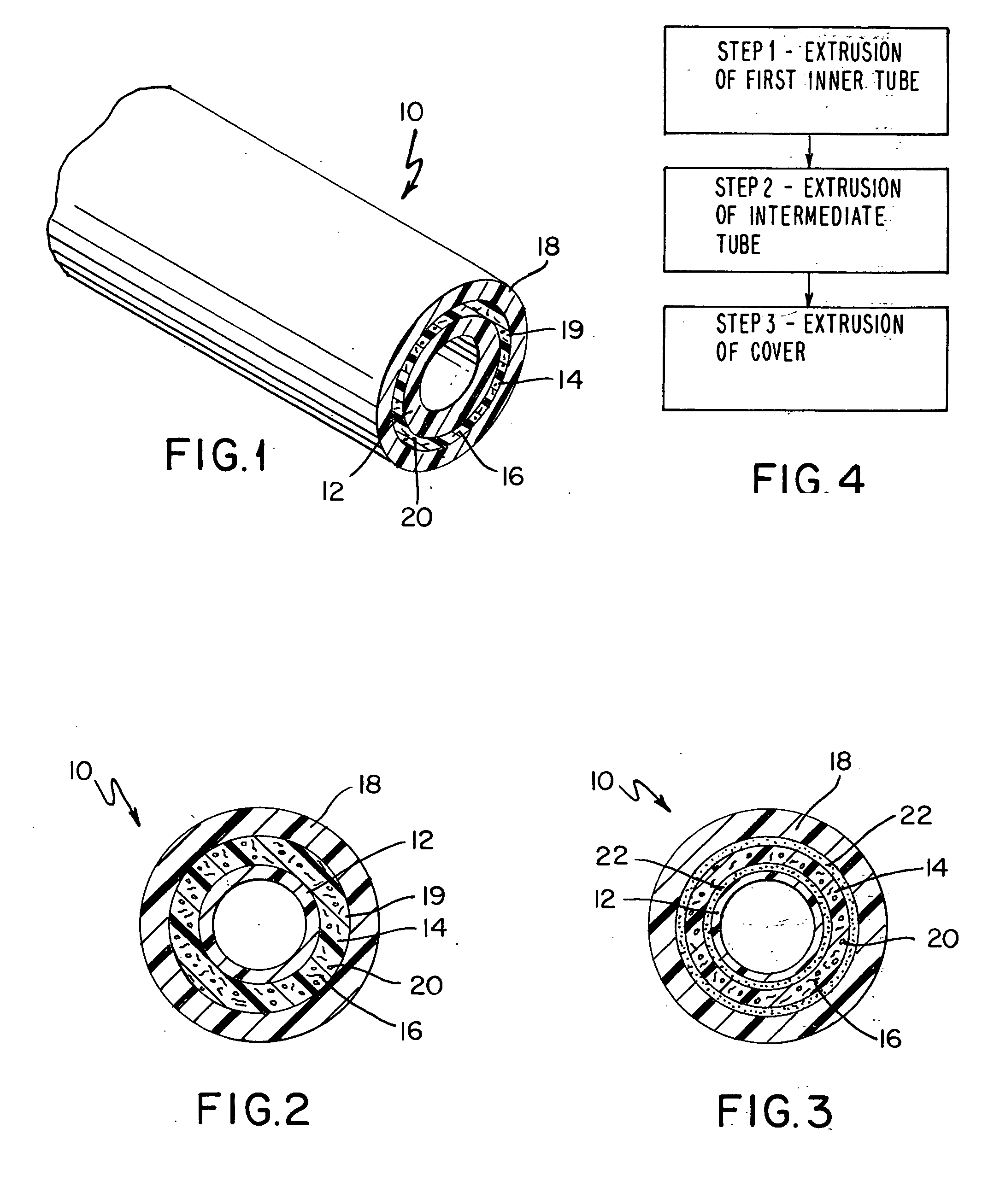
[0015] The present coolant hose is a multi-layered construction comprising a first tubular structure having an inner surface and an outer surface; a second polymeric tubular structure having an inner surface and an outer surface wherein the inner surface of the second tubular structure is adhered to the outer surface of the first tubular structure; and a third polymeric tubular structure having an inner surface and an outer surface wherein the inner surface of the third tubular structure is adhered to the outer surface of the second tubular structure. In accordance with the present invention, the second tubular structure, which is intermediate the first tubular structure, and the third tubular structure, is a foamable tubular structure which further comprises a plurality of reinforcement elements in the form of short fibers dispersed therein. It has been found that if the short reinforcement elements are incorporated into a foamable polymeric composition, the foaming action during e...


PUM

PropertyMeasurementUnit
Lengthaaaaaaaaaa
Lengthaaaaaaaaaa
Lengthaaaaaaaaaa

Abstract

A multi-layered tube comprising a first inner polymeric tubular structure, a second foamed polymeric structure containing a plurality of short or long reinforcing elements dispersed therein and, optionally, a third cover layer on the outer surface of the reinforcing layer; and a method for manufacturing the multi-layered hose are disclosed.

Description

RELATED APPLICATION [0001] Filed concurrently with this application is U.S. Ser. No. ______ to Cleveland et al. entitled “Multi-Layered Hose”.BACKGROUND OF THE INVENTION [0002] The present invention relates to tubular structures and particularly to flexible tubular structures such as coolant hoses for use in the automotive industry, and to the manufacture of such tubular structures. [0003] Tubular structures, in general, are constructed from various polymeric materials such as chlorinated polyethylene (CPE); chlorosulfonated polyethylene (CSM); natural rubber; synthetic rubber such as ethylene acrylic copolymer (AEM); styrene-butadiene rubber (SBR), neoprene, ethylene-propylene rubber (EPR), butyl rubber, polybutadiene, polyisoprene, nitrile-butadiene rubber (NBR), polybutylene, ethylene-propylene diene terpolymers (EPDM) and the like; blends of such natural and synthetic rubbers; vulcanizable blends of natural and synthetic rubbers; blends of natural and / or synthetic rubbers with, ...

Claims


Application Information

Patent Timeline
IPC IPC(8): B32B1/08F16L11/10
CPCB32B1/08Y10T428/1372Y10T428/1393F16L11/10B32B27/065B32B37/15B32B2307/738B32B27/24B32B2597/00B32B2305/08
Inventor CLEVELAND, RAFAEL L.DAVIS, ANDREW R.
Owner FLUID ROUTING SOLUTIONS
Why Eureka
Try Eureka