Vehicle-mounted display unit

a display unit and vehicle technology, applied in the field of display units, can solve problems such as not showing the degree of warning

Active Publication Date: 2005-08-04
YAZAKI CORP
View PDF8 Cites 52 Cited by
  • Summary
  • Abstract
  • Description
  • Claims
  • Application Information

AI Technical Summary

Benefits of technology

[0018] In view of the aforementioned situation, an object of the present invention is to provide a vehicle-mounted display unit enabling a comprehensive indication of measured values showing vehicle running speed and engine revolution simultaneously with other additional information of a motor vehicle.
[0023] Preferably, the control device controls the display such that the maintenance indication includes a pointer shorter than the normal length one. Thereby, the display system allows a normal meter indication including engine revolution speed and vehicle running speed simultaneously with indication of information different from the normal meter indication. The changeover between the longer pointer and the shorter one provides a new design of a meter that is advantageous in visuality and compactness.
[0029] Thereby, the display system allows a normal meter indication including engine revolution speed and vehicle running speed simultaneously with indication of information different from the normal meter indication. The changeover between the longer pointer and the shorter one provides a new design of the meter that is advantageous in visuality and compactness.
[0030] Preferably, the control device changes the length of the pointer such that a distal end of the pointer is constant in its radial distance from a pivot of the pointer. Thus, the pointer does not interfere with the indication of additional information in the auxiliary indication area, improving the information in clarity.
[0031] Preferably, the control device changes the length of the pointer such that the pointer is changed from a longer one to a shorter one via an intermediate length one. This provides a new design of the meter for a driver who can recognize the shortening step of the pointer.

Problems solved by technology

However, the conventional display system of FIG. 14 is disadvantageous in design of a meter and an instrument panel for indicating a great amount of information which requires a large symbol displaying space.
Furthermore, the predetermined indication pattern of FIG. 14 can not show the degree of warning.

Method used


Image

  • Vehicle-mounted display unit
  • Vehicle-mounted display unit
  • Vehicle-mounted display unit

Examples


Embodiment Construction

[0045] Referring to the accompanied drawings, embodiments of a vehicle-mounted display unit according to the present invention will be discussed hereinafter.

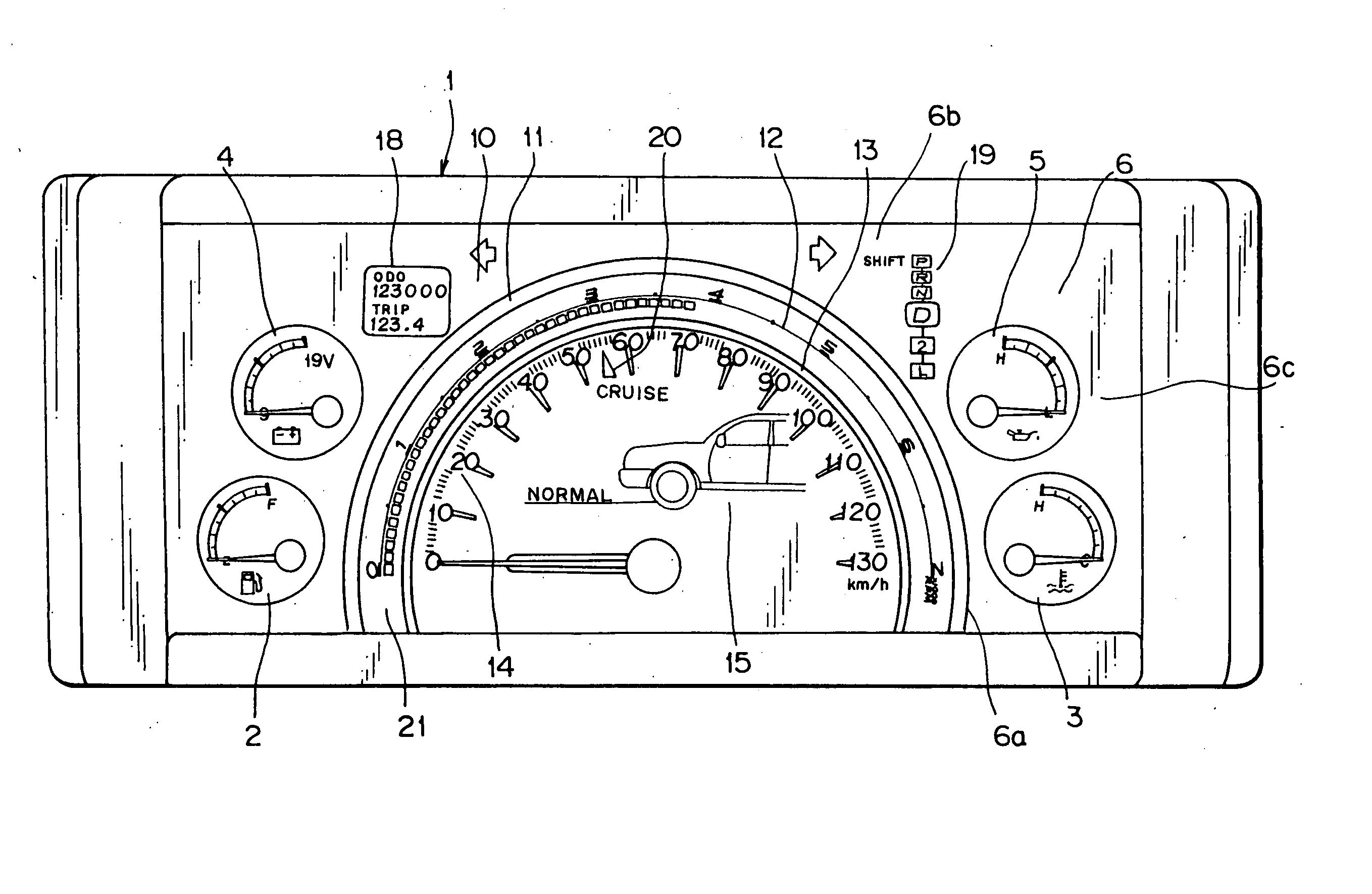
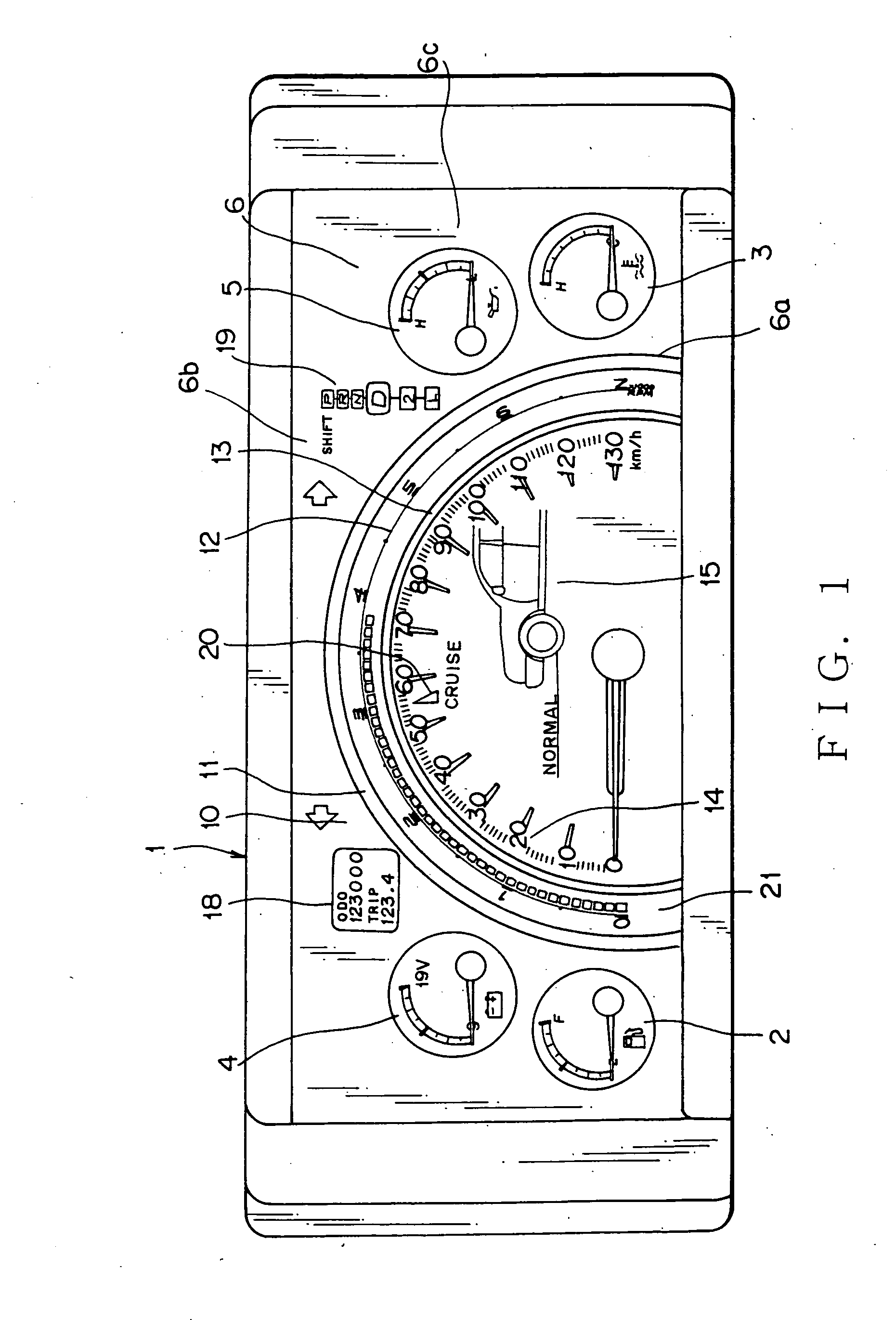
[0046] In FIG. 1, a vehicle-mounted display unit 1 has a meter display 10 disposed at a front central area thereof. Around the meter display 10, there are arranged a plurality of independent analog indicators, which are a fuel meter 2 indicating a residual amount of a liquid fuel such as gasoline, a meter 3 indicating a temperature of a cooling water, a battery voltage meter 4 indicating voltage thereof, and a pressure meter 5 showing pressure of engine oil.

[0047] The meter display 10 is constituted by a liquid-crystal display (LCD), an electro-luminescence device, a cathode-ray tube, or the like. In this embodiment, an LCD is applied. The meter display 10 indicates various information of operational conditions of the motor vehicle on its screen.

[0048] The screen has a semi-circular dial for showing measured values of operati...


PUM


Abstract

The vehicle-mounted display unit includes a display having a meter area and an auxiliary indication area. The meter area indicates a dial image for showing measured values of an operational condition of a motor vehicle. The auxiliary indication area indicates information other than the measured values. The display unit has a control device for controlling contents indicated on the display. The control device indicates a normal length pointer extended in the auxiliary indication area at a normal indication state, while the control device indicates a shorter length pointer in the auxiliary indication area when the other information is indicated.

Description

BACKGROUND OF THE INVENTION [0001] 1. Field of the Invention [0002] The present invention relates to a display unit mounted on a motor vehicle. [0003] 2. Related Art [0004] A conventional display unit of such a type is disclosed in Japanese Patent Application Laid-open No. 2001-191816, which was proposed by the same applicant as the present application. [0005]FIG. 14 is an explanatory view showing a general configuration of a screen of the conventional vehicle-mounted display unit. The display unit watches abnormal states of a battery, a radiator, and an engine which are disposed in a bonnet of a motor vehicle. The system has a warning indication area 103 that selectively turns on each of warning symbols 103a, 103b, 103c, and 103d for warning an abnormal state of a charge quantity of the battery, a cooling water of the engine, a lubricating oil pressure of the engine, or an electronic control process of the engine. The screen indicates not only a specified content of an abnormal sta...

Claims


Application Information

Patent Timeline
IPC IPC(8): B60K35/00B60Q1/00G01D11/28G01P1/08
CPCB60K35/00B60K37/02G01P1/08B60K2350/1072G01D11/28B60K2350/1064B60K35/60B60K35/213B60K35/215
Inventor ONO, SHUNSUKEMURAMATSU, MASAHIROMATSUO, YOSHIHARU
Owner YAZAKI CORP
Why Eureka
Try Eureka