Combustion type power tool having segmental connection unit

a power tool and segmental connection technology, applied in the direction of manufacturing tools, stapling tools, nailing tools, etc., can solve the problem of unnecessary storage, and achieve the effect of enhancing workability and enhancing material yieldability

Inactive Publication Date: 2005-08-04
KOKI HLDG CO LTD
View PDF16 Cites 1 Cited by
  • Summary
  • Abstract
  • Description
  • Claims
  • Application Information

AI Technical Summary

Benefits of technology

[0008] It is therefore an object of the present invention to provide a combustion type power tool enhancing workability as well as enhancing yieldability to a material.
[0010] Since the connection unit is provided by the connector section and separate arm sections, the connector section and the arm sections can be made independently of each other by punching plate members. Accordingly, yieldability for connector sections and for arm sections can be improved in the punching. Further, since the entire connection unit including the connector section and the arm sections assembled thereto is covered within the housing, the sliding component having a high temperature is not directly exposed to outside. Thus a user can be protected against direct touching to the high temperature component.
[0011] Preferably, the biasing member is at a position out of alignment with an axis of the cylinder. With this structure, a surplus space between the outer peripheral surface of the cylinder and the housing becomes unnecessary for installing the biasing member. As a result, a diameter of the housing can be reduced, and asssembleability of the combustion type power tool can be improved.

Problems solved by technology

With this structure, a surplus space between the outer peripheral surface of the cylinder and the housing becomes unnecessary for installing the biasing member.

Method used


Image

  • Combustion type power tool having segmental connection unit
  • Combustion type power tool having segmental connection unit
  • Combustion type power tool having segmental connection unit

Examples


Embodiment Construction

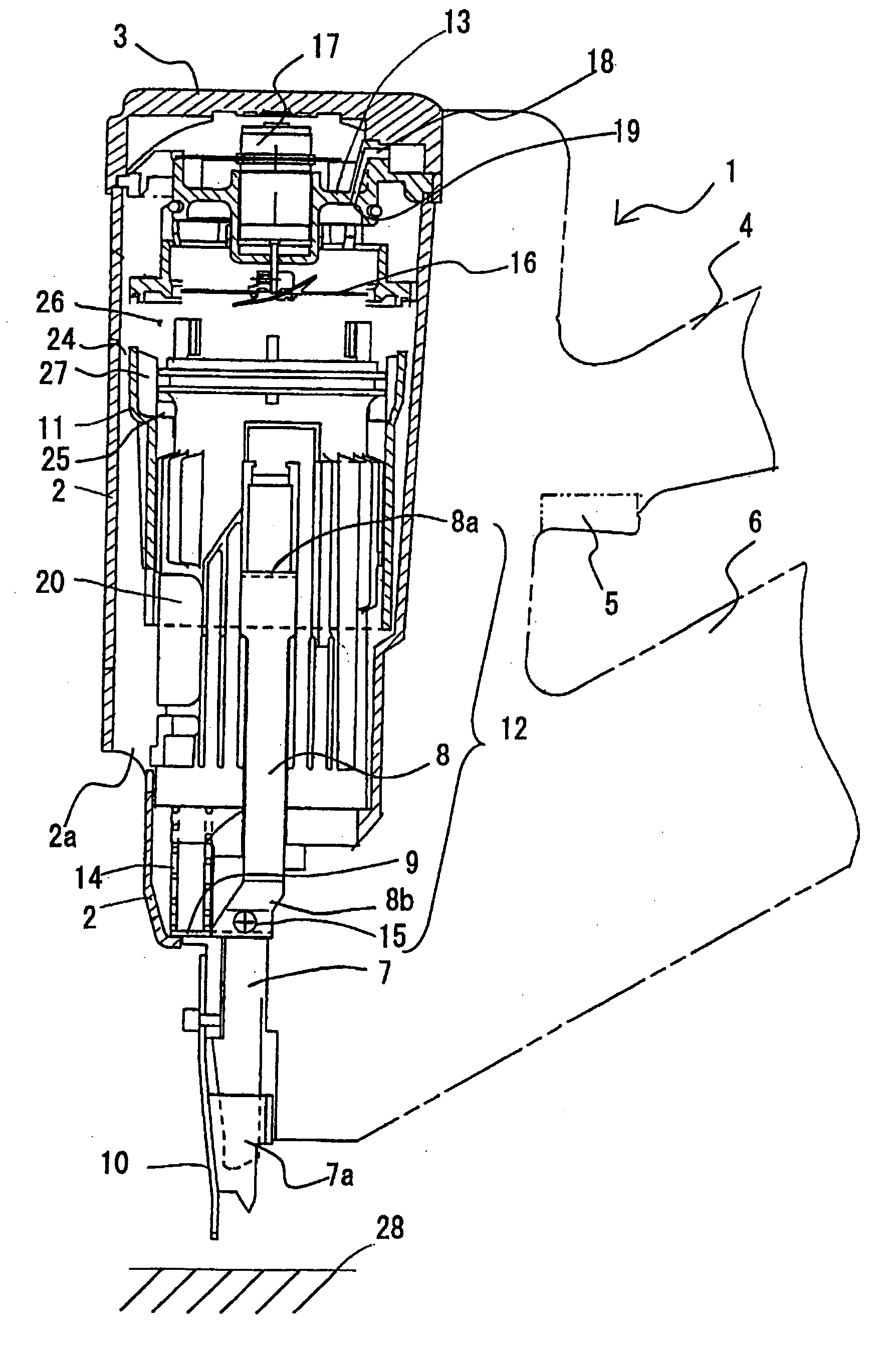
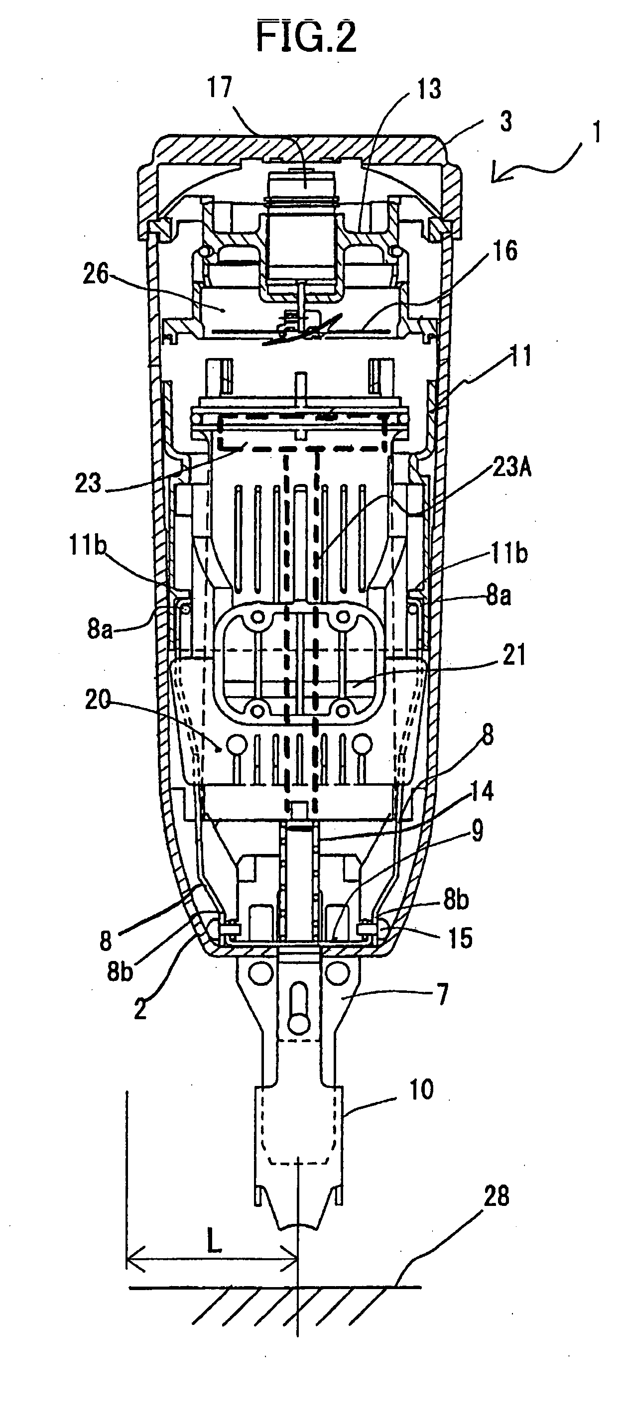
[0022] A combustion-type power tool according to one embodiment of the present invention will be described with reference to FIGS. 1 through 5. The embodiment pertains to a combustion type nail driver. The combustion type nail driver 1 shown in FIG. 1 has a housing 2 constituting an outer frame. The housing 2 has a lower portion formed with an exhaust port 2a. A head cover 3 formed with an intake port (not shown) is mounted on the top of the housing 2. A handle 4 extends from one side of the housing 2. The handle 4 has a trigger switch 5 and detachably accommodates therein a battery (not shown). A canister housing portion (not shown) is formed in the housing 2 and at the one side thereof from which the handle 4 extends. A gas canister (not shown) containing therein a combustible liquidized gas is detachably installable in the canister housing portion. A magazine 6 accommodating therein a bundle of nails (not shown) is disposed below the handle 4.

[0023] A nose 7 extends from near th...


PUM

PropertyMeasurementUnit
angleaaaaaaaaaa
outer diameteraaaaaaaaaa
diameteraaaaaaaaaa

Abstract

A combustion type power tool providing enhanced workability and improved material yieldability. A combustion chamber frame is slidably movably disposed in a housing. A push lever is slidably movably supported to a nose extending from a lower end portion of the housing, and is abuttable on a workpiece. The combustion chamber frame and the push lever are associated with each other by a connection unit including arm sections and a connector section. A compression coil spring for biasing the push lever downwardly is interposed between the connector section and a cylinder disposed in the housing. The housing covers the entire arm sections, the connector section and the spring, so that these components are not directly accessible from an outside.

Description

BACKGROUND OF THE INVENTION [0001] The present invention relates to a combustion-type power tool having a combustion chamber frame, a push lever and a connection unit. [0002] A conventional combustion-type driving tool such as a nail gun is disclosed in U.S. Pat. No. 5,197,646. In the disclosed driving tool, a spring serving as a biasing member is positioned at a lower portion of the tool for urging a push lever downwardly toward a workpiece. A spring seat protrudes from an outer peripheral surface of a cylinder, so that the spring is seated on the spring seat and interposed between the spring seat and a housing serving as an outer frame of the nail gun. The spring urges an arm portion provided integrally with the push lever for biasing the push lever downwardly. [0003] In the above-described conventional combustion type power tool, since the spring is interposed between the outer peripheral surface of the cylinder and the housing for urging the push lever downwardly, a surplus spac...

Claims


Application Information

Patent Timeline
Patent Type & Authority Applications(United States)
IPC IPC(8): B25C1/08
CPCB25C1/08
Inventor AKIBA, YOSHITAKA
Owner KOKI HLDG CO LTD
Why Eureka
Try Eureka