
Transducer assembly for ultrasound probes

a technology of ultrasound probes and assembly parts, which is applied in the field of ultrasound probe assembly, can solve the problems of imposing size and space constraints on the probe, and the need to rotate the transducer

Inactive Publication Date: 2005-07-28
KONINKLIJKE PHILIPS ELECTRONICS NV
View PDF11 Cites 111 Cited by
  • Summary
  • Abstract
  • Description
  • Claims
  • Application Information

AI Technical Summary

Benefits of technology

[0010] It is another object of the present invention to provide a new and improved ultrasound probe including a transducer assembly which does not have to rotate to obtain multi-planar, volumetric three-dimensional images.
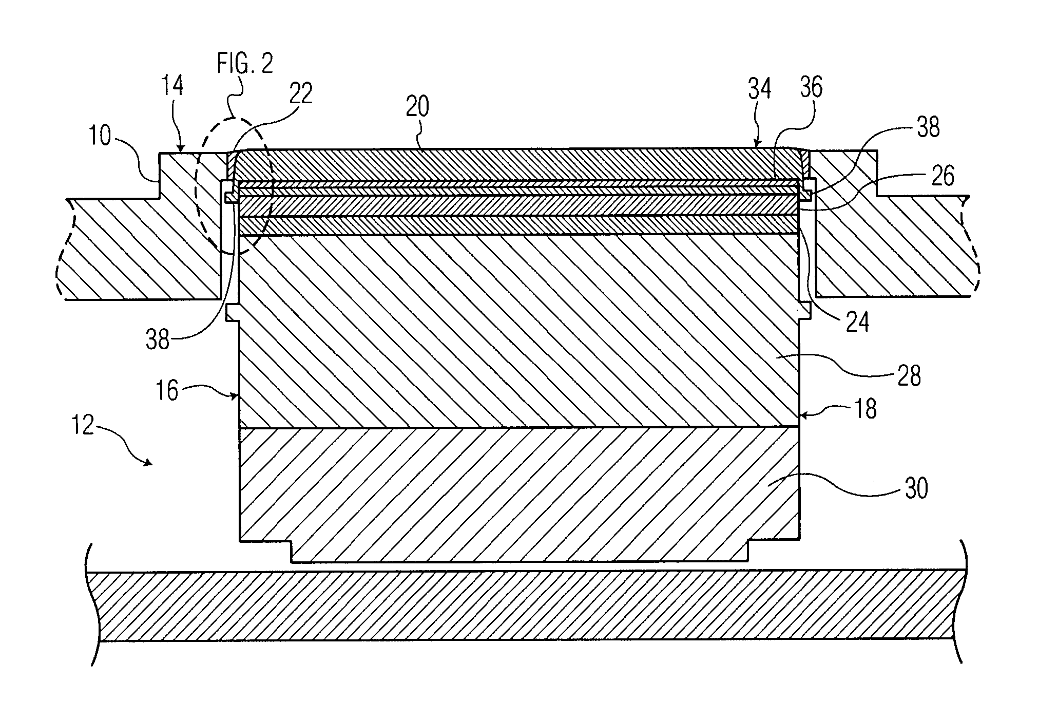
[0017] An ultrasound probe in accordance with the invention includes a housing defining a cavity extending inward from an opening in a peripheral surface, a transducer array as described above arranged in the cavity of the housing to produce ultrasound beams and an acoustic window attached directly to the transducer array such that the transducer array and the acoustic window form an integral unit. The housing may be in any form of a medical imaging device including in the form of a housing of a transesophageal echocardiographic ultrasound probe or transnasal probe, or a nose for a transthoracic, intracavity or intraoperative probe. The combination of the housing and the cushion of the integral window further serve to protect the array from impact (biting by the patient in particular).
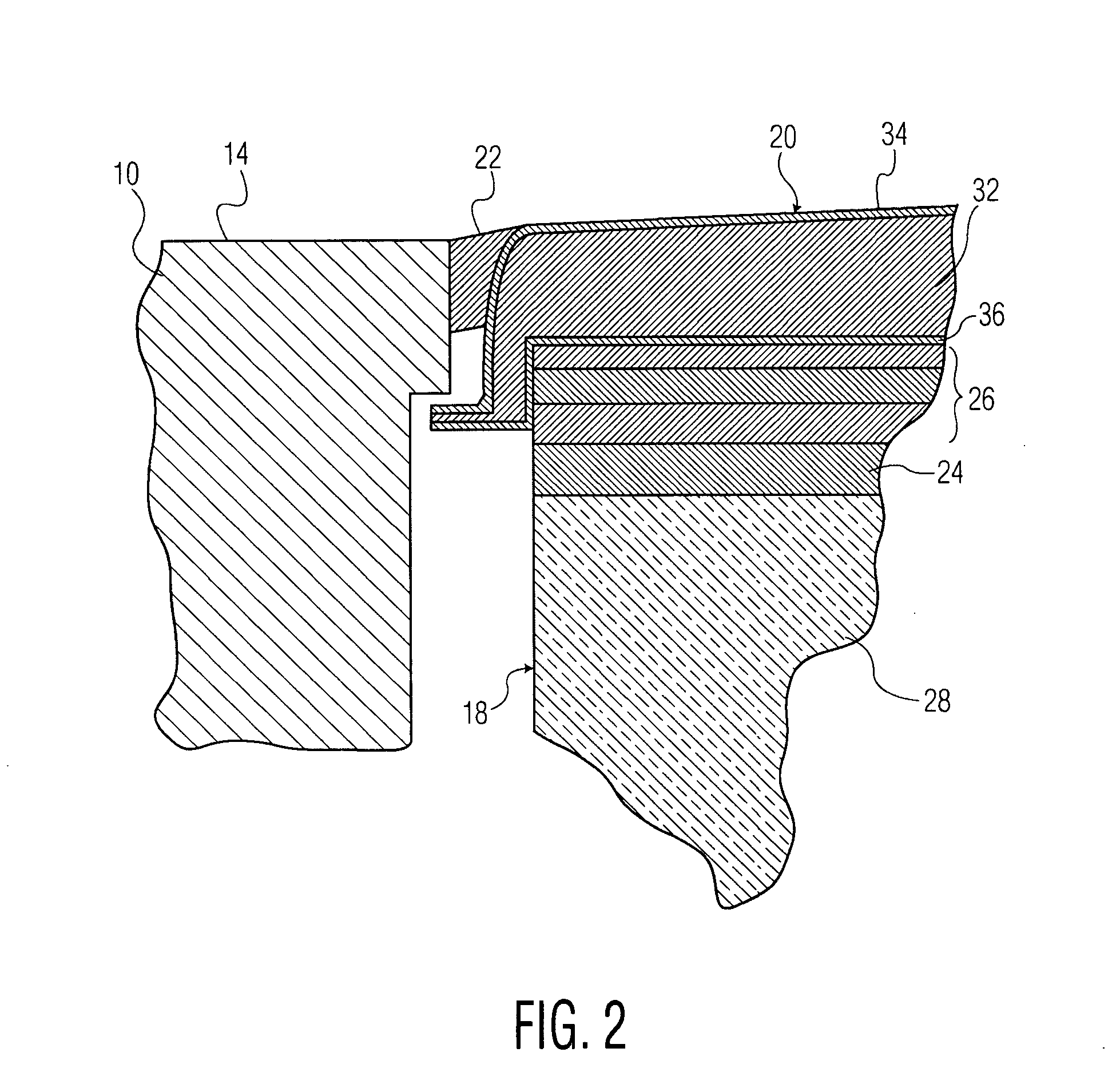
[0018] A flexible seal is interposed between the acoustic window and the housing to seal the cavity and prevent the entry of fluids into the cavity. The flexibility of the seal also enables it to absorb impacts into the acoustic window without breaking.

Problems solved by technology

A drawback of such prior art TEE probes is that it is necessary to rotate the transducer array to obtain multi-planar images of the object being examined in the patient's body.
This associated structure imposes size and space constraints on the probe.

Method used


Image

  • Transducer assembly for ultrasound probes
  • Transducer assembly for ultrasound probes
  • Transducer assembly for ultrasound probes

Examples


Embodiment Construction

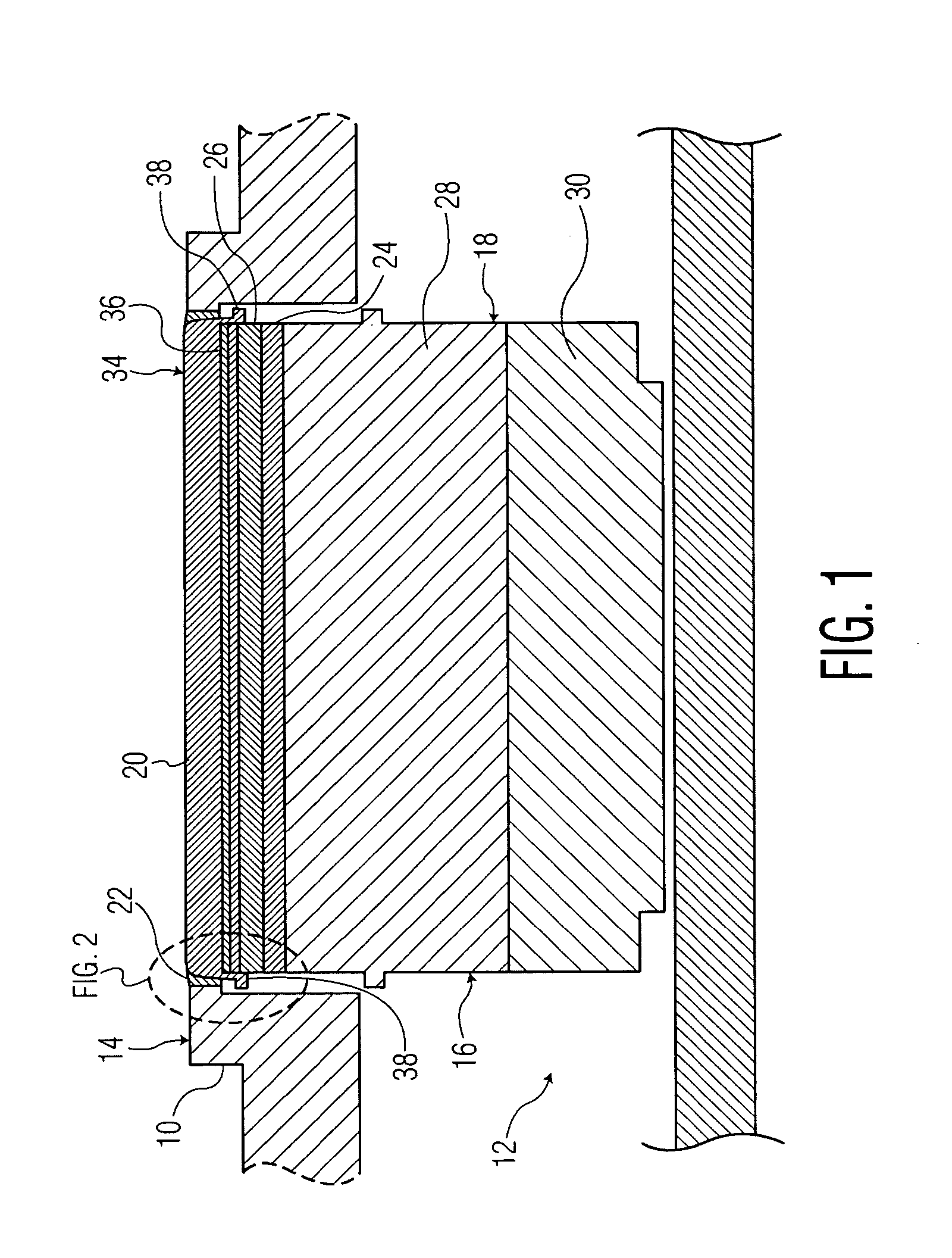
[0028] Referring to the accompanying drawings wherein like reference numerals refer to the same or similar elements, an ultrasound probe in accordance with the invention includes a housing 10 defining a cavity 12 extending inward from an opening in a peripheral surface 14 and a transducer assembly 16 arranged in the cavity 12. Housing 10 can be shaped in the form of any type of TEE, transthoracic, intracavity or transnasal probe. Housing 10 and the transducer assembly 16 in accordance with the invention can also be used in any imaging device in the medical field.

[0029] Transducer assembly 16 includes a transducer array 18 and an acoustic window 20 attached or bonded directly to the transducer array 18. The direct attachment or bonding of the acoustic window 20 to the transducer array 18 may be accomplished through the use of an adhesive or other suitable means known in the art. By attaching the acoustic window 20 directly to the transducer array 18, a transducer assembly with an in...


PUM


Abstract

Transducer assembly for an ultrasound probe including a transducer array having transducer elements and an acoustic window attached directly to the transducer array such that the transducer array and the acoustic window form an integral unit. The acoustic window includes a layer of elastomer optionally covered on upper and lower surfaces by impervious polymer layers. An ultrasound probe, such as a transesophageal echocardiographic probe, a transnasal probe, a transthoracic probe, an intracavity probe and an intraoperative probe, including the transducer assembly in a cavity of the housing or nose is also disclosed.

Description

CROSS REFERENCE TO RELATED CASES [0001] Applicants claim the benefit of Provisional Application Ser. No. 60 / 539,300, filed 26 Jan. 2004.FIELD OF THE INVENTION [0002] The present invention relates generally to ultrasound probes and more particularly to a transducer assembly for ultrasound probes including an integral acoustic window. BACKGROUND OF THE INVENTION [0003] Ultrasound probes are commonly used for imaging internal body parts. One type of ultrasound probe includes a transducer array mounted in a body and having an active surface oriented toward an acoustic window connected to the body and which is separate from the transducer array. The body is usually made of hard plastic and is referred to as a housing for transesophageal echocardiographic or TEE probes and as a nose for transthoracic or intracavity probes. Thus, while the term housing will be used hereinafter in connection with the description of the invention below, it should be understood that when applied to ultrasound...

Claims


Application Information

Patent Timeline
Patent Type & Authority Applications(United States)
IPC IPC(8): A61B8/14G10K11/02
CPCG10K11/02
Inventor BYRON, JACQUELYN M.B.KNOWLES, HEATHER BECK
Owner KONINKLIJKE PHILIPS ELECTRONICS NV
Learn More