Method for detecting biochemical reactant biochip
a biochemical and reactant technology, applied in the field of biochemical reactant detection, can solve the problems of fluorescent dye extinction, differences in efficiency, complex modifying operation of fluorescent labels, etc., and achieve the effects of improving the accuracy of detection of object specimens, simplifying the detection step, and good reproducibility
- Summary
- Abstract
- Description
- Claims
- Application Information
AI Technical Summary
Benefits of technology
Problems solved by technology
Method used
Image
Examples
example 1
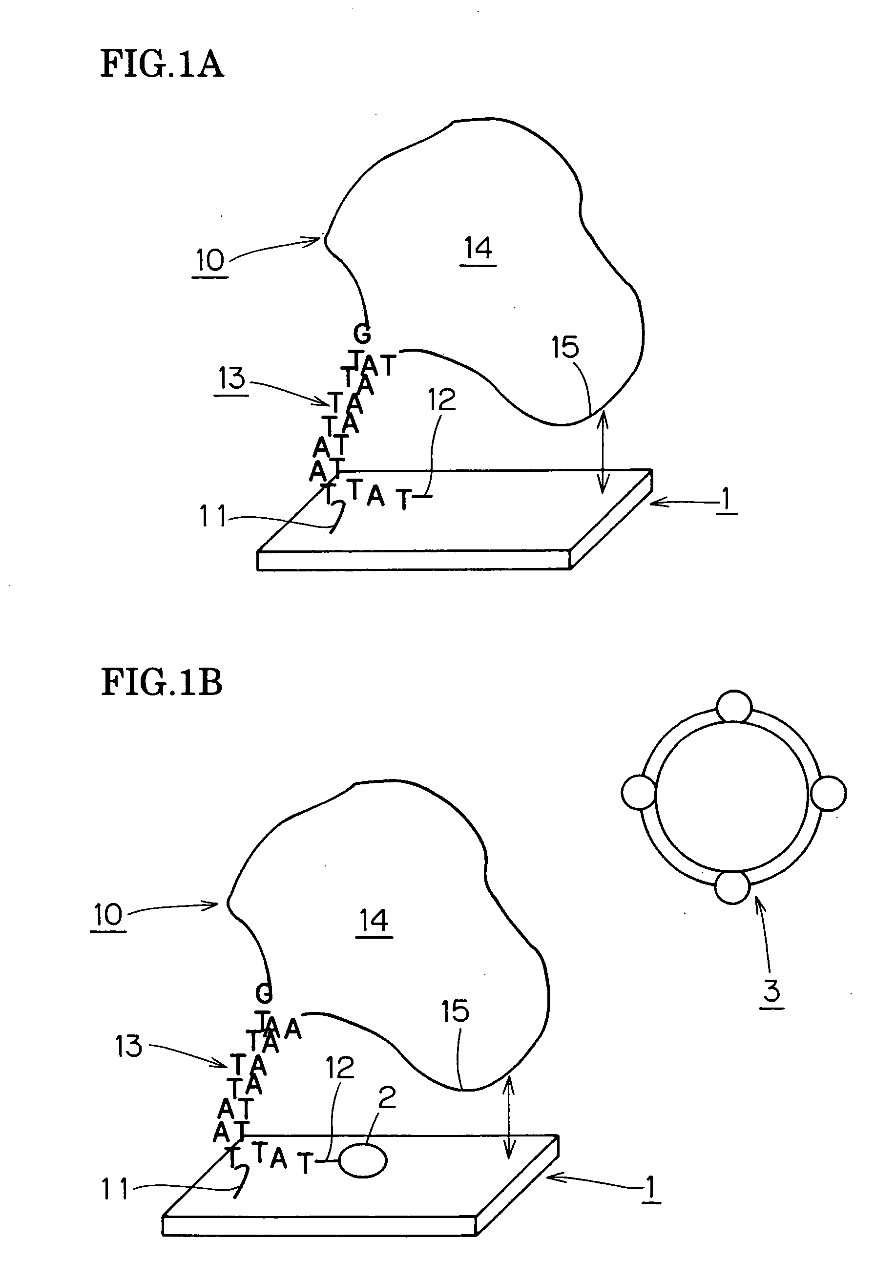
[0127] The object of detection was about 856 bp of DNA surrounding a mutation in the Campylobacter jejuni O-19 serum gyrB gene, and 60 central nucleotides of RNA which bound complementarily to this at the central part was prepared as probe RNA. Three types of probe DNA were prepared for purposes of comparison—30 terminal nucleotides of DNA which bound complementarily with the aforementioned DNA at the terminus, 30 central nucleotides of DNA which bound complementarily with the central part, and 60 central nucleotides of DNA. The 30-nucleotide probes were configured so as not to form loops within the same chain, and the 60-nucleotide probes so as to form loops within the same chain.
[0128] A glass substrate was used as the substrate for preparing the biochip. This was ultrasonically washed in acetone, methanol and ultra-pure water, surface washed for 20 seconds with 10% hydrofluoric acid, washed again ultrasonically in acetone, methanol and ultra-pure water and dried with nitrogen ga...
example 2
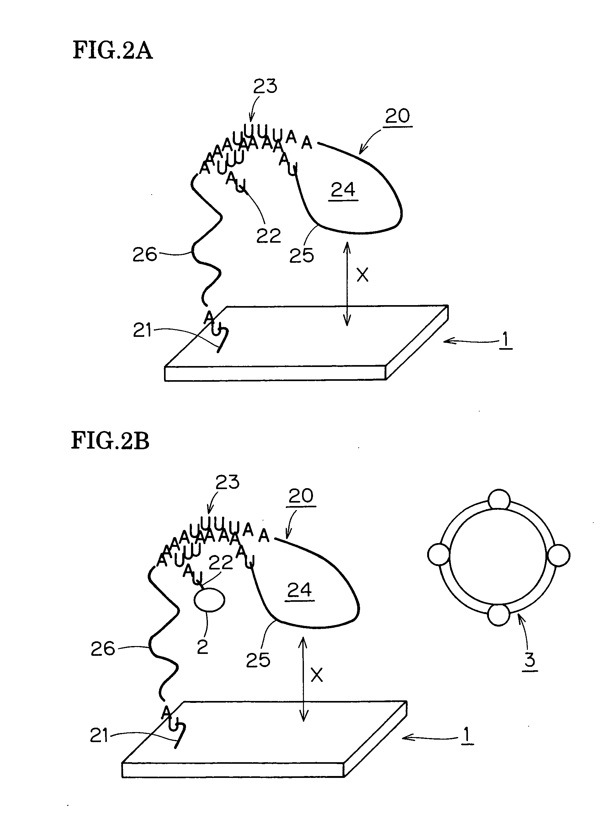
[0140] RNA was used in place of the DNA of Example 1 as the object of detection. That is, about 800 nucleotides of RNA prepared by in-vitro RNA synthesis from the gyrB gene (Campylobacter jejuni) was purified and used.
[0141] 60 nucleotides of DNA which bound complementarily in the center with the aforementioned synthetic RNA was used as the probe DNA, and was arrayed under similar conditions and on a similar glass substrate as in Example 1 to prepare a biochip.
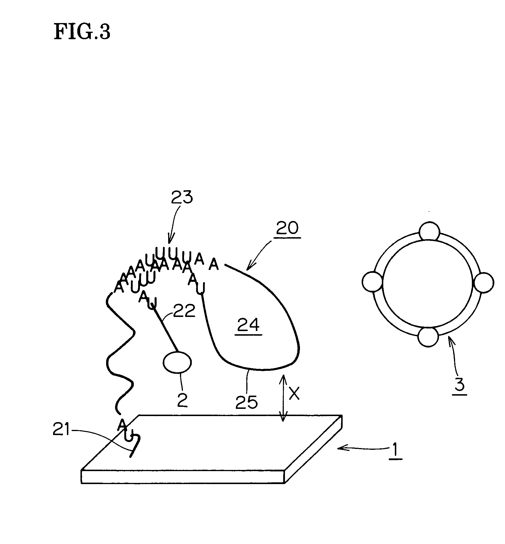
[0142] In the gold colloid modification method adopted here for attaching the label the aforementioned biochip was washed after hybridization with R-BFR solution and gently dried with nitrogen gas, and gold colloid (particle size 10 nm, SIGMA) coated with avidin was dripped and left for 1 to 3 hours in saturated steam to modify using the specific binding of biotin and avidin.
[0143] Moreover, metal fine particle modification was performed using a pH 7.4 colloidal solution of Fe fine particles with a mean particle size of abo...
example 3
[0150] In place of the aforementioned gold or Fe fine particles used in Example 2, the probe DNA was modified with pH 7.4 colloidal silica, using silica particles which were coated in advance with avidin so that they would bind by biotin-avidin binding with the 5′ end of the biotin-modified probe. A variety of particle sizes between 100 nm and 800 nm were present in the colloidal silica.
[0151] In the mechanism for detecting hybridization in the scanning device, a detection chip was mounted on a prism, He—Ne laser light was directed at the underside of the substrate from one side of the prism and totally reflected to the other side of the prism, and the strength of scattered light was detected by a CCD camera observing from the upper surface of the biochip.
[0152] For purposes of comparison, modification was performed without the aforementioned hybridization using a silica fine particle label coated with avidin. In the results, no modification with the silica fine particle label occ...
PUM
| Property | Measurement | Unit |
|---|---|---|
| grain size | aaaaa | aaaaa |
| grain size | aaaaa | aaaaa |
| grain size | aaaaa | aaaaa |
Abstract
Description
Claims
Application Information
 - R&D
- Intellectual Property
- Life Sciences
- Materials
- Tech Scout
- Unparalleled Data Quality
- Higher Quality Content
- 60% Fewer Hallucinations
Browse by: Latest US Patents, China's latest patents, Technical Efficacy Thesaurus, Application Domain, Technology Topic, Popular Technical Reports.
© 2025 PatSnap. All rights reserved.Legal|Privacy policy|Modern Slavery Act Transparency Statement|Sitemap|About US| Contact US: help@patsnap.com


