
Scanning apparatus and method for full page scans

a full-page scan and scanning apparatus technology, applied in the field of image recording apparatus, can solve the problems of undesirable inclusion of housing edge in scan data, undesirable arbitrary deletion of some portion of data near the image edge, and no useful data is likely to be deleted, so as to eliminate the oversight, difficulties, and disadvantages.

Inactive Publication Date: 2005-07-28
LEXMARK INT INC
View PDF14 Cites 1 Cited by
  • Summary
  • Abstract
  • Description
  • Claims
  • Application Information

AI Technical Summary

Benefits of technology

[0013] With regard to the foregoing, the present invention eliminates the oversights, difficulties, and disadvantages of the prior art by providing an improved apparatus and method of full page scanning.

Problems solved by technology

However, inclusion of a housing edge in the scan data is undesirable because an unsightly line or artifact is produced on the copy or included in the saved data.
In other words, no useful data is likely to be deleted.
If a borderless full page image is scanned, arbitrary deletion of some portion of data near the image edge may be undesirable.
Thus one can clearly understand that deletion of useful scanned data is undesirable.

Method used


Image

  • Scanning apparatus and method for full page scans
  • Scanning apparatus and method for full page scans
  • Scanning apparatus and method for full page scans

Examples


second embodiment

[0039] As previously indicated, the present invention overcomes the problem of capturing data which represents the platen aperture 44. In order to overcome this problem, the instant invention utilizes a pattern 80 which extends along an edge of the platen aperture 44, as seen in FIG. 3. The present invention effectively inserts a known pattern 80 into a scanned image and, according to one embodiment, the processor 56 subsequently removes the pattern 80 from the scanned data before exporting the scanned data to, for instance, a host PC or before printing the image. the scanned pattern 80 may be included in the scanned data and removed by a user of the host PC. The multifunction peripheral 10 may also include the means necessary to remove the pattern 80 from the scanned data.

first embodiment

[0040] As shown in FIG. 3, one illustrative embodiment of the present invention utilizes a pattern 80 positioned on a lower surface of the raised edge or lip 34. For purpose of simplicity, the pattern 80 is not shown extending along the entire length of each edge 34 of platen aperture 44 but is intended to do so as shown in FIGS. 5 and 6. Referring still to FIG. 3, the pattern 80 may be molded or the pattern 80 may be painted or screen printed on the raised edge 34. the pattern 80 is molded into the raised edge 34 defining a plurality of ridges 82 which extend along the raised edge 34. The ridges 82 may define some preselected shape including bars, dots, or other pattern defining shapes. The image sensor 74 may read the ridges 82 when the scanbar 60 passes over the ridges 82. In a first alternative embodiment, the ridges 82 may be painted or printed, for instance screen-printed, with some color which contrasts the color of the molded edge 34. With a contrasting color, the image sen...


PUM


Abstract

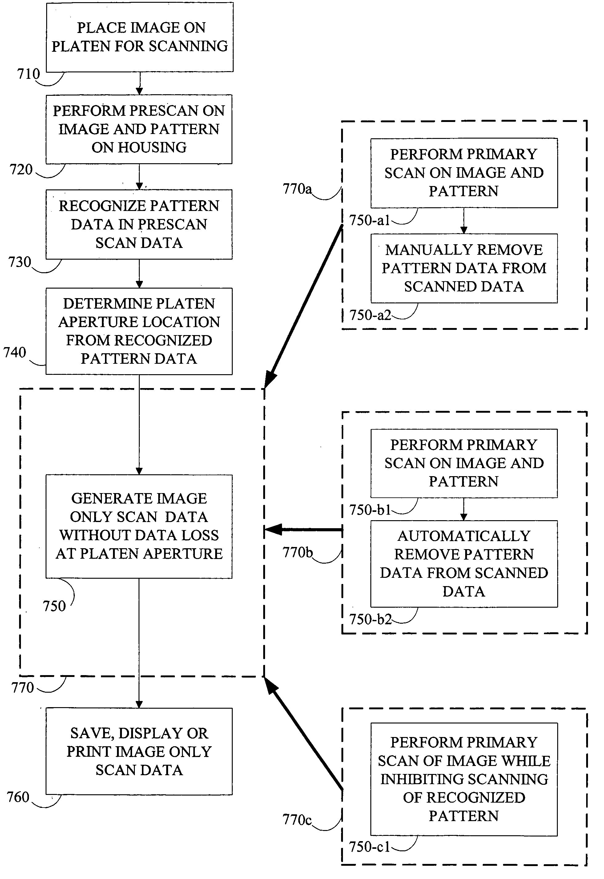
The present invention provides, an improved scanning apparatus and method for full-page scanning. The apparatus comprises a flat-bed scanner having a pattern disposed on a lower surface of the scanner housing. More specifically the pattern may be produced on a raised edge defining a platen aperture on a surface of the scanner housing. The pattern is recognized by the scanbar and processor so that the scanner can distinguish between a platen aperture edge and a document or image during a full-page scan. The present method comprises making a prescan to recognize and locate the platen aperture. Next, a primary scan is performed and scanned data is produced. During the primary scan, the scanbar may not scan the pattern. Alternatively, the scanbar may scan the pattern and subsequently remove the pattern from the scanned data. According to another method, the scanner may make a single scan collecting the pattern and the image. Subsequently, a processor may remove the pattern and, therefore the platen aperture edge from the scanned data.

Description

CROSS REFERENCES TO RELATED APPLICATIONS [0001] The application is related to U.S. Patent Application Ser. No. ______ filed Jan. 9,2004, entitled “SCANNER AND METHOD FOR SCANNING AN IMAGE OR IMAGES and assigned to the assignee of the current application.STATEMENT REGARDING FEDERALLY SPONSORED RESEARCH OR DEVELOPMENT [0002] None. REFERENCE TO SEQUENTIAL LISTING, ETC. [0003] None. BACKGROUND [0004] 1. Field of the Invention [0005] The present invention relates to an improved apparatus and method of full page scanning. More particularly, the present invention relates to an image recording apparatus having a flat-bed scanner including a pattern on a surface of a scanner housing so that a scanbar may recognize a housing edge. [0006] 2. Description of the Related Art [0007] Scanners are used to scan a target image to create a scanned image which can be displayed on a computer monitor, which can be used by a computer program, which can be printed, which can be faxed, etc. Scanned data may ...

Claims


Application Information

Patent Timeline
IPC IPC(8): H04N1/00H04N1/10H04N1/193H04N1/40
CPCH04N1/00795H04N1/00816H04N2201/0416H04N1/1017H04N1/193H04N1/00819
Inventor OWENS, BRIAN K.SPITZ, DONALD N.
Owner LEXMARK INT INC
Learn More