
Active backscatter wireless display terminal

a wireless display terminal and backscatter technology, applied in the direction of program control, instruments, testing/monitoring control systems, etc., can solve the problems of low signal strength, limited range, and need for a larger power supply and generation, and achieve effective communication range, low heat dissipation, and cost-effective

Inactive Publication Date: 2005-07-28
AGILE DISPLAYS LLC
View PDF30 Cites 13 Cited by
  • Summary
  • Abstract
  • Description
  • Claims
  • Application Information

AI Technical Summary

Benefits of technology

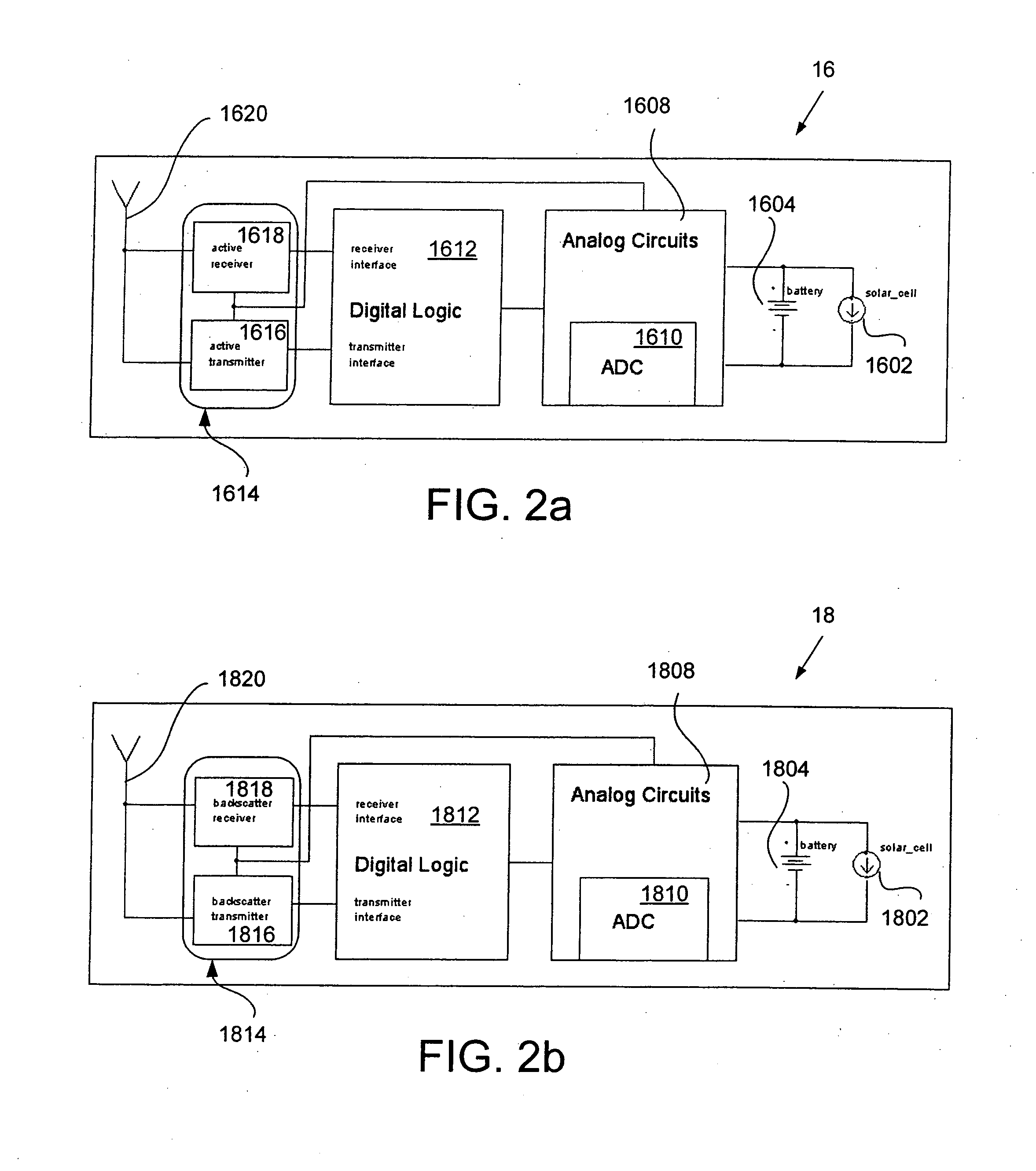
This combination achieves lower power consumption and effective communication range with reduced heat dissipation, allowing for a compact and cost-effective design that can adapt to varying communication needs.

Problems solved by technology

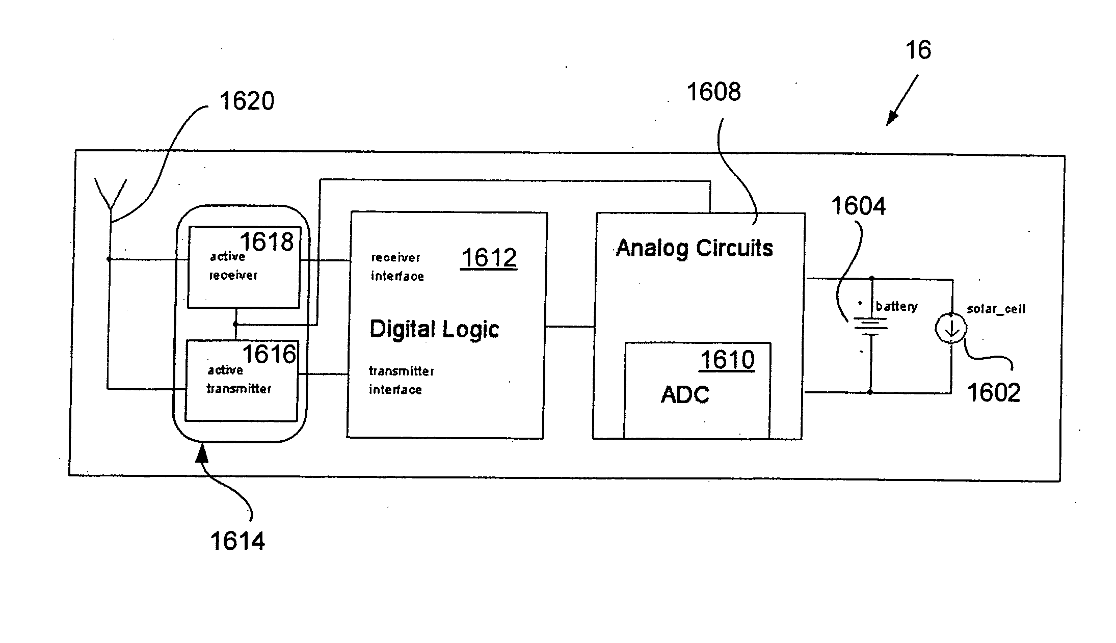
However, the use of an active power source results in the need for a larger power supply and generation of heat, both of which are concerns in compact circuitry designs.
However, the problem with the backscatter transceivers is that the signal strength is low and, hence, the range is very limited.
Thus, backscatter transceivers are not always effective when longer transmission range is desired.

Method used


Image

  • Active backscatter wireless display terminal
  • Active backscatter wireless display terminal
  • Active backscatter wireless display terminal

Examples


Embodiment Construction

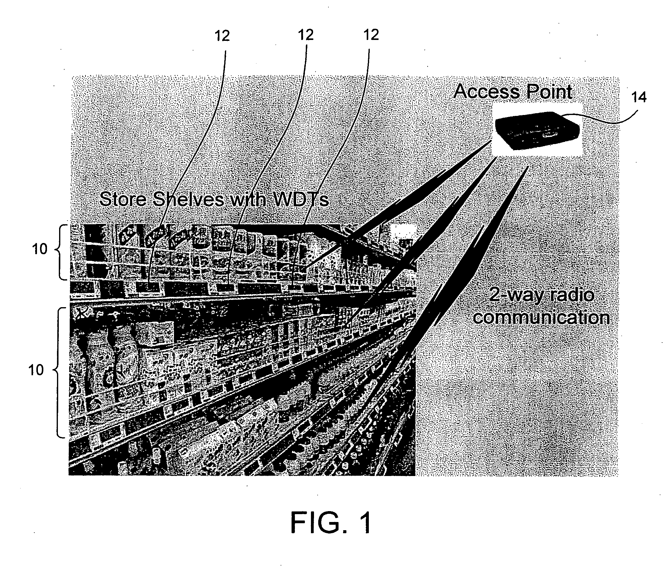
[0037] Referring now to FIG. 1, retailers place products 10 on shelves and indicate the pricing of the products 10 using display units or Wireless Display Terminals (WDTs) 12. The display units 12 are typically located on shelf edges and display price and other information to aid the consumer as well as the store employees. Although in the present embodiment, the WDT 12 is shown positioned at the shelf edge, the WDT 12 can be located on peg hooks or near products as set forth in U.S. Provisional Application Ser. No. 10 / ______ titled ______ filed on even date herewith; U.S. Provisional Application Ser. No. 10 / ______ titled filed on even date herewith; and U.S. Provisional Application Ser. No. 10 / ______ titled ______ filed on even date herewith, all of which are incorporated herein by reference.

[0038] Each of the WDTs 12 communicate via radio frequency with a wireless access point device or Access Point (AP) 14. The AP 14 can be placed at any convenient location in the store that all...


PUM


Abstract

A wireless display tag, adapted to fit within the C-channel of a shelf-edge, or otherwise usable as a hang tag or small identification device, includes, depending on implementation, an active transceiver, a passive transceiver, or both, with analog and digital control portions for managing communications with a host.

Description

RELATED APPLICATIONS [0001] The present invention claims the benefit of priority from the following U.S. provisional applications: U.S. patent Ser. No. 60 / 530,819 filed Dec. 18, 2003 entitled “Wireless Display Tag (WDT) Using Amplified Backscatter”; U.S. patent Ser. No. 60 / 530,818 filed Dec. 18, 2003 entitled “Wireless Display Tag (WDT) Using an Active Transmitter”; U.S. patent Ser. No. 60 / 530,817 filed Dec. 18, 2003 entitled “Wireless Display Tag (WDT) Using an Active Receiver”; U.S. patent Ser. No. 60 / 530,816 filed Dec. 18, 2003 entitled “Wireless Display Tag (WDT) Using an Active Transmitter and Diode Receiver”; U.S. patent Ser. No. 60 / 530,795 filed Dec. 18, 2003 entitled “Wireless Display Tag (WDT) Using Active and Backscatter Transceivers”; U.S. patent Ser. No. 60 / 530,790 filed Dec. 18, 2003 entitled “Wireless Display Tag (WDT) Unit”; U.S. patent Ser. No. 60 / 530,783 filed Dec. 18, 2003 entitled “RF Backscatter Transmission with Zero DC-Power Consumption”; U.S. patent Ser. No. 6...

Claims


Application Information

Patent Timeline
Patent Type & Authority Applications(United States)
IPC IPC(8): G06F1/16G06K15/00G06K19/07G09G3/00H01P5/12H04B1/00H04B1/59H04B5/48H04L5/16
CPCG06K19/0707G06K19/0712G09G2380/04G06K19/07703G09G3/001G06K19/0723
Inventor GOEL, ANURAGSAXENA, SUNITMCDONALD, MARK DOUGLASDORFMAN, LEONARD MARK
Owner AGILE DISPLAYS LLC
Learn More