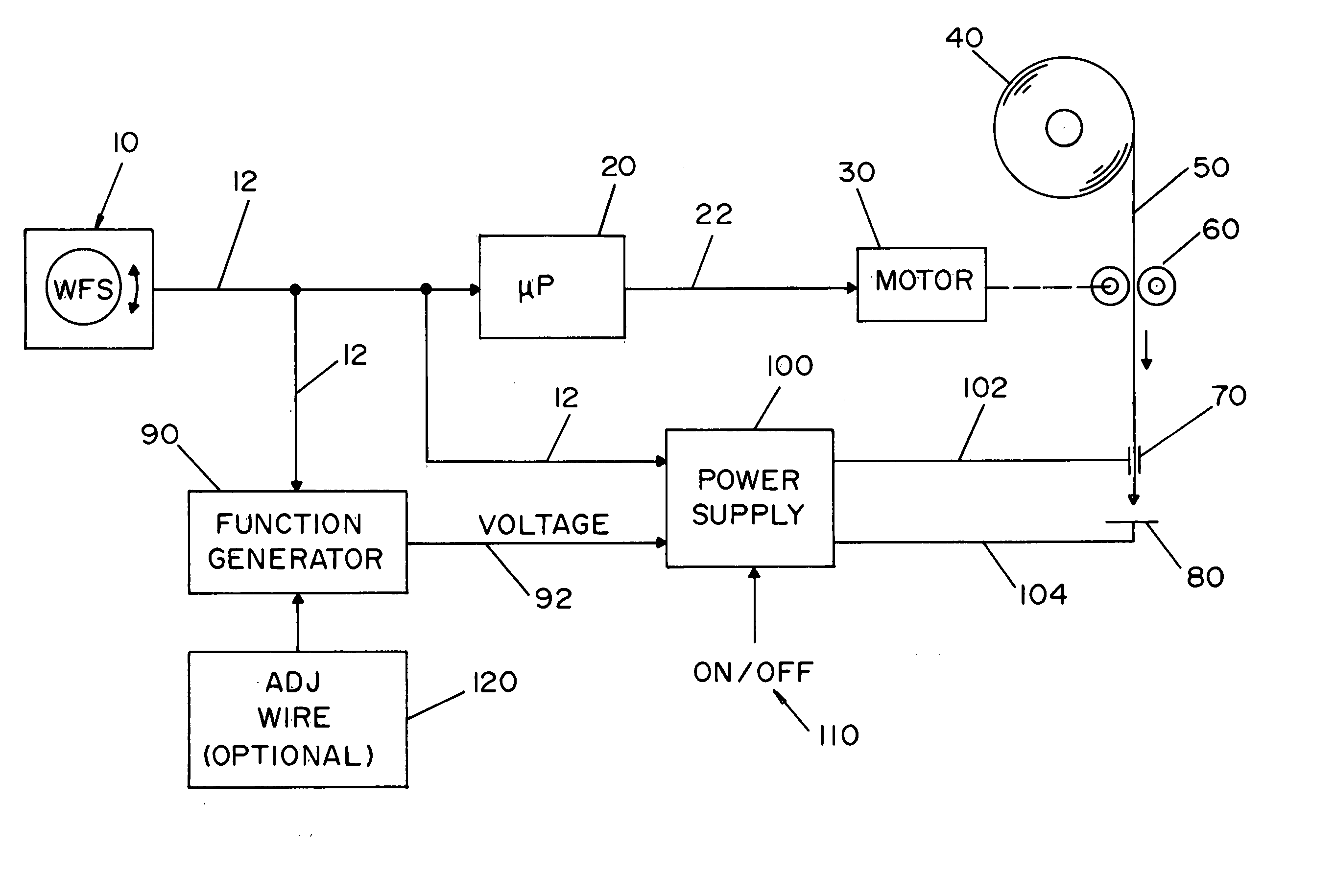
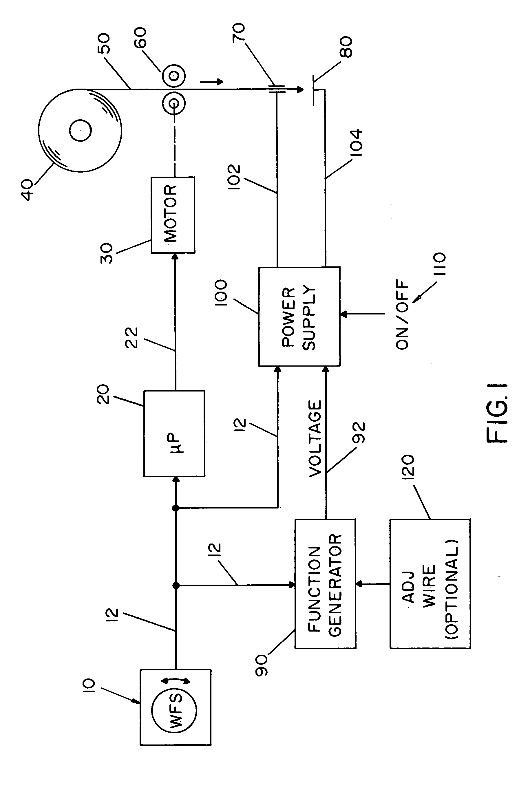
[0006] In accordance with one aspect of the present invention, there is provided a welder having a welding power source, a wire feeder and a wire feed speed controller. The welder is designed particularly for MIG (
solid wire and gas) applications. The welder has a simplified design in that the welder includes a single wire feed control that controls both the wire feed speed of the consumable
electrode and the
arc welding voltage and / or current level of the welding power source. As a result, the welder of the present invention significantly simplifies the
welding process by enabling an operator to select a particular wire feed speed which selection automatically generates an appropriate
arc welding voltage and / or current level for the selected wire feed speed. In one embodiment of the invention, the wire feed speed selector generates a
signal that is used by a wire feed speed controller to control the actual wire feed speed of an
electrode being fed to a workpiece. The wire feed speed selector is typically a
potentiometer that generates a linear
signal; however, a non-linear
signal can be generated by the
potentiometer. As can be appreciated, the wire feed speed selector can be a digital selector or any other type of selector which can generate a
control signal. The
control signal generated by the wire feed speed selector is typically directed to a hard wire circuit and / or a
microprocessor which converts the signal into a control current or
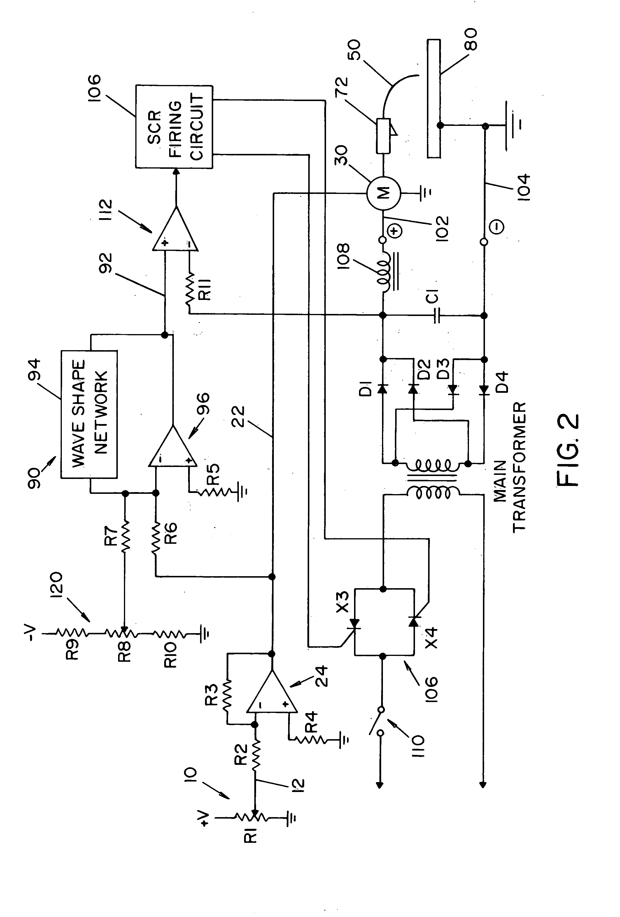
voltage used to drive the motor of a wire feeder. As can be appreciated, the signal from the wire feed speed selector can be used to directly control the motor of the wire feeder. In another and / or alternative aspect of the invention, the signal generated by the wire feed speed selector is directed to a welding output controller that in turn generates a signal to the welding power source control SCRs, FETs, IGBTs, etc., to control the
arc welding voltage and / or current. The welder output controller is designed to increase or decrease the
arc voltage and / or current generated by the power supply of the arc welder as the wire feed speed control is changed. This particular control design for an arc welder enables the operator to control both the wire feed speed and the arc welding voltage and / or current by a single control knob or selector. This simplified design results in reduced manufacturing costs of the welder by reducing the number of parts, and simplifies a welding operation by reducing the number of control knobs on the welder.
[0011] In still another and / or alternative aspect of the present invention, there is provided a welder which includes one or more controls designed to adjust the control signal generated by the
function generator. The use of a particular
diameter of electrode, type of electrode, and / or
shielding gas mixture can affect the quality of the weld. In the simplest design of the arc welder in accordance with the present invention, the welder includes a single control knob or selector to adjust the wire feed speed during a welding operation and uses the signal from the selected wire feed speed to also control the arc welding voltage and / or current generated by the welding power supply. In this particular design, an operator simply increases or decreases the wire feed speed for a particular welding application. The
function generator of the
wave shape network in the welder can be factory set for a nominal
arc voltage-arc current relationship. For instance, the welding
machine could be designed for use with a 0.035 inch
diameter low carbon
solid wire which uses a
shielding gas mixture of about 75%
argon and 25%
carbon dioxide. So long as an operator uses this particular type of welding wire having this particular
diameter in conjunction with this particular
shielding gas mixture, a desired
weld bead will be formed. However, if the operator deviates from these factory set parameters, the quality of the
weld bead may be reduced. In order to accommodate the use of different types of welding wire, different diameters of welding wire and / or different types of shielding gases, the welder of the present invention may include one or more manual switches or selections used to define the type of electrode, the size of the electrode and / or the type of shielding gas used in a particular welding operation, and thereby appropriately change the output
function generator of the
wave shape network. In one embodiment of the invention, one or more manually controlled switches or selectors are inserted on the arc welder to enable an operator to select a particular type of electrode, a particular size of electrode and / or a particular type of shielding gas. In another and / or alternative embodiment of the present invention, the arc welder includes one or more internal switches or controllers designed to automatically detect the type of electrode being used, the diameter of the electrode being used and / or the type of shielding gas being used and automatically change or modify the output of the function generator of the
wave shape network in accordance with one or more of these detected values. In this particular design of the welder, the simplicity of the welder is maintained since the operator still uses only a single wire feed speed knob or selector to control the wire feed speed and the arc welding voltage and / or current of the welder. Any modification to the relationship between the selected wire feed speed and the arc welding voltage and / or current is automatically adjusted based upon the detected electrode type, electrode diameter and / or shielding gas type by the welding
machine.
[0012] The primary object of the present invention is the provision of an apparatus and method of welding that is simple and cost effective to use.
[0017] A further and / or alternative object of the present invention is the provision of an apparatus and method of welding that is simpler to use than previously available arc welders.
[0018] Still a further and / or alternative object of the present invention is the provision of an apparatus and method of welding that includes a welder having less user-selectable controls so as to simplify a welding procedure.
[0019] Still yet a further and / or alternative object of the present invention is the provision of an apparatus and method of welding that includes a low cost welder having a simplified
user control arrangement and which produces a high quality
weld bead during a welding operation.


