
Wheelchair Passenger Securement System With Movable Bumper

a passenger and passenger technology, applied in the field of vehicles with wheelchair passenger securement systems, can solve the problems of increasing installation costs, increasing the cost of installation (more components and labor), and reducing the safety of wheelchair passengers, so as to eliminate a potential tripping hazard and eliminate an obstacle for wheelchair passengers

Active Publication Date: 2019-05-09
VALEDA
View PDF0 Cites 7 Cited by
  • Summary
  • Abstract
  • Description
  • Claims
  • Application Information

AI Technical Summary

Benefits of technology

The patent describes a system for securing a wheelchair to a vehicle that is simpler and safer than previous systems. It uses fewer attachment points, reducing the chance of injury, and takes up less installation time and maintenance. The system also eliminates potential tripping hazards for non-wheelchair passengers and obstacles for wheelchair passengers. Overall, the system provides greater safety and efficiency for vehicles transporting wheelchair passengers.

Problems solved by technology

The prior art four-point systems are considered by many to be relatively cumbersome and time-consuming to secure, especially if the system is used on a public transit vehicle where dwell times are critical.
The prior art four-point systems suffer from numerous problems or short-comings.
The use of the additional aisle-side restraint increases the cost of installation (more components and labor), poses a significant obstacle and tripping hazard for wheelchairs and other passengers, and requires more time to secure the chair (increasing vehicle dwell time and the potential for driver injuries while attempting to secure the device).
Some have attempted to solve this problem by mounting the aisle-side restraint device to a retractable arm, such as the one disclosed in U.S. Pat. No. 5,888,038, but such a system adds unnecessary expense and still poses a potential tripping hazard.
Others have attempted to vary from the traditional four-point systems with limited success.
However, this system still suffers from the same problems as the traditional four-point system since it also requires the use of a coupling, or some other device, such as a “Y” belt (see reference number 48 in U.S. Pat. No. 6,113,325).
Therefore, such systems are still relatively cumbersome and time-consuming to use.
Plus, these systems are inherently weaker than the traditional four-point systems (four vehicle attachment points / four wheelchair attachment points) since they utilize only one restraint device to secure the rear of the wheelchair, where more strength is required to sufficiently restrain the wheelchair during emergency braking events.
Also, if the coupling or “Y” belt is not permanently attached, there is the potential to lose the component, rendering the system useless.
In fact, it is believed that such a configuration may actually increase dwell time and potential for driver injury as compared to traditional four-point systems.
Even further, the configuration of these prior art systems are quite complex, which increases the opportunity to use it improperly.
It should not be forgotten that driver error is one of the most predominant causes of wheelchair tip-overs in the industry.
However, this prior art system utilizes manually operable restraints and coffers, or covered floor pockets, that are bulky, difficult to use, can pose a significant tripping hazard, and require an extra installation as compared to the embodiments described herein.
Like the prior art system of the '325 patent, the system disclosed in the '644 patent also only uses a single vehicle attachment point to secure the rear of the wheelchair and is therefore inherently weak.

Method used


Image

  • Wheelchair Passenger Securement System With Movable Bumper
  • Wheelchair Passenger Securement System With Movable Bumper
  • Wheelchair Passenger Securement System With Movable Bumper

Examples


first embodiment

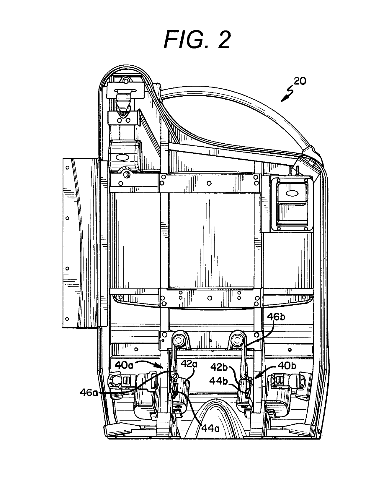
[0051]In the first embodiment, the wheelchair securement system 10 is best characterized as a drop-in system for a vehicle which is fully-equipped to secure a wheelchair and its passenger in a forward facing orientation (i.e., with respect to the direction of travel of the vehicle). In this orientation, the barrier module 20 is forward-facing (i.e., positioned rearward of the side-wall module 30 in the vehicle) and secures the wheelchair at two attachment points at the rear of the wheelchair. Although shown in a configuration suitable for installation adjacent a right side wall of a vehicle, the system 10 could be configured as a mirror image of the shown configuration for installation adjacent a left side wall of the vehicle. The side-wall module 30 is positioned adjacent to a wall of the vehicle and secures the wheelchair at a single attachment point at the front of the wheelchair. The barrier module 20 and side-wall module 30, through the use of three points of attachment to the ...

second embodiment

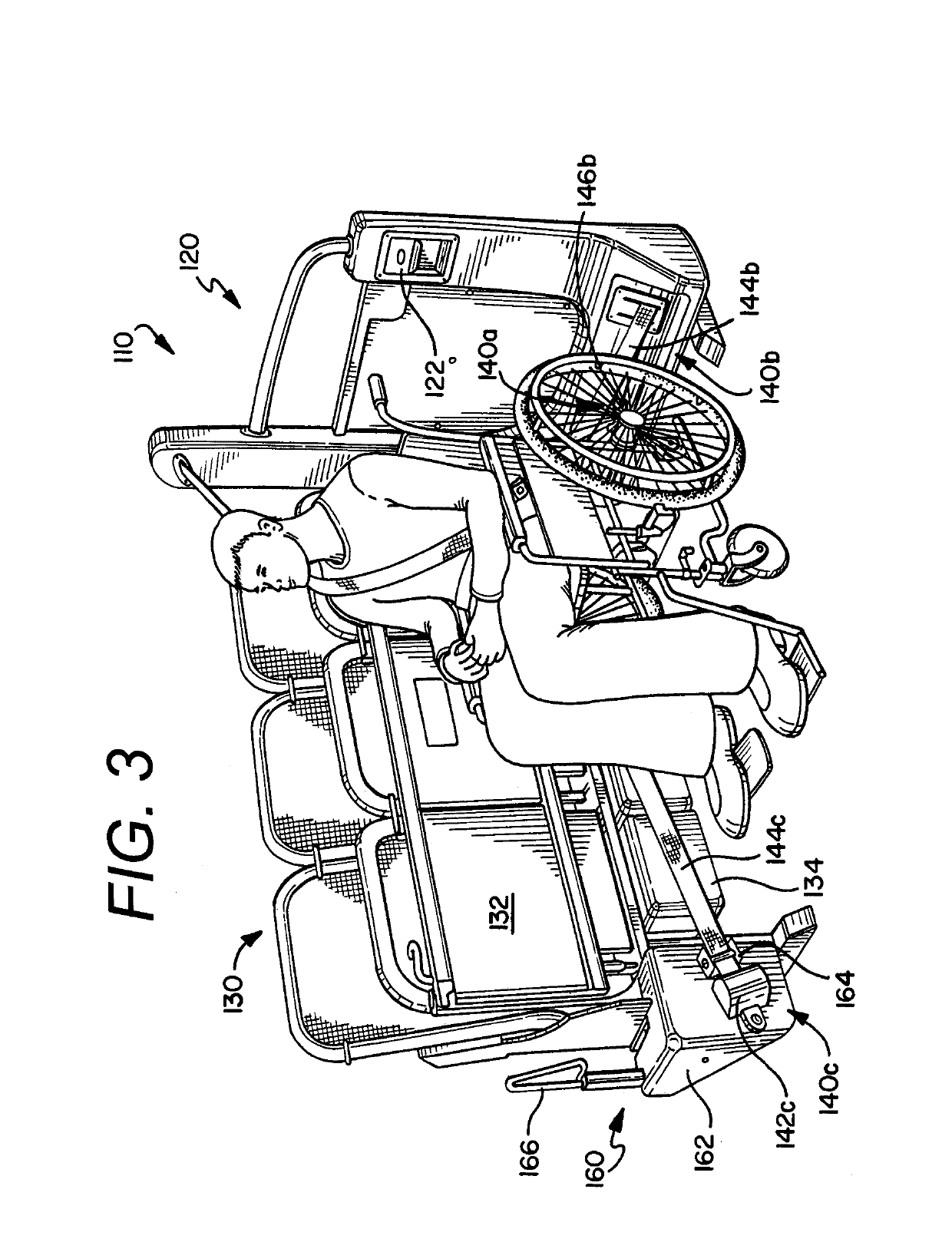
[0061]In the shown embodiment, it is contemplated that the side barrier 34 would have resilient properties, wherein it would have some give, but still provide firm support for the wheelchair. In an alternative embodiment, the side barrier 34 could be biased outward using, for example, a spring that pushes the side barrier 34 outward. When the front restraint 40c was hooked up and would pull the chair in, the springs would provide an opposing force to stabilize the chair. As discussed below at least in the context of the second embodiment, the side barrier 34 could also be mechanized or inflatable, wherein it is movable to positively contact the wheelchair and induce pre-tension into the securement assemblies 40a, 40b, 40c.

[0062]With reference now to FIGS. 3-4, a second embodiment of a wheelchair securement system 110 is shown. Like the first embodiment, the second embodiment includes a barrier module 120 and a side-wall module 130 that are substantially similar to those described i...

sixth embodiment

[0081]As with some of the previous embodiments, the barrier module 620 includes a remote control device (or timed release mechanism) with a release latch (or paddle handle or release handle) 622 for releasing one or more of the securement assemblies 640a, 640b, 640c, such as any one of the systems described in U.S. provisional patent application Ser. No. 60 / 705,452, U.S. provisional patent application No. 60 / 618,572, U.S. patent application Ser. No. 11 / 252,326, and / or PCT patent application no. PCT / US06 / 30085. In the shown embodiment, paddle handle 622 releases the locking mechanisms of retractors 642a, 642b for a predetermined amount of time, which is sufficient for the vehicle operator to engage / release the fasteners 646a, 646b with / from the wheelchair.

[0082]Proper restraint of a wheelchair in the sixth embodiment of the system 610 can be achieved using the following steps. First, the side seat should be placed and locked in the folded, upward position. Second, the wheelchair is m...


PUM


Abstract

The embodiments described and claimed herein are improved wheelchair passenger securement systems and stations. In particular, one embodiment described and claimed herein is a system that includes a wheelchair restraint and a moveable bumper, wherein the movable bumper is configured to induce tension into the wheelchair restraint.

Description

CROSS-REFERENCE TO RELATED APPLICATIONS[0001]This application is a continuation of and claims priority to:[0002]co-pending U.S. application Ser. No. 14 / 811,248, entitled “Wheelchair Passenger Securement System With Bumper,” filed on Jul. 28, 2015;[0003]which is a continuation of U.S. application Ser. No. 13 / 842,407, entitled “3-Point Wheelchair Passenger Securement System”, filed on Mar. 15, 2013, now U.S. Pat. No. 9,107,786 which was granted on Aug. 18, 2015;[0004]which is a continuation-in-part of U.S. application Ser. No. 12 / 573,881, entitled “3-Point Wheelchair Passenger Securement System”, filed Oct. 5, 2009, now U.S. Pat. No. 8,414,234 which was granted on Apr. 9, 2013;[0005]which claims priority to U.S. Provisional Patent Application No. 61 / 102,853, entitled “3-Point Wheelchair Passenger Securement System” filed Oct. 5, 2008.[0006]Together, U.S. application Ser. Nos. 14 / 811,248, 13 / 842,407, 12 / 573,881, and 61 / 102,853 are hereby incorporated by reference.STATEMENT REGARDING FE...

Claims


Application Information

Patent Timeline
Patent Type & Authority Applications(United States)
IPC IPC(8): A61G3/08B60R22/24B60R22/20B60R22/22B60P3/079
CPCA61G3/0808B60R22/22B60R22/24B60P3/079B60R22/20A61G2203/723B60P7/08
Inventor GIRARDIN, JEAN-MARCESTEIREIRO, JOE
Owner VALEDA
Learn More