
Full digital dimming ballast for a fluorescent lamp

a fluorescent lamp and full digital technology, applied in the field of ballast, can solve the problems of lack of intelligent pre-heating features, design that does not provide short-circuit or load-fault protection, and ballasts utilizing digital controllers lack some of the functionalities of regular analog ballasts

Active Publication Date: 2005-07-21
SEMICON COMPONENTS IND LLC
View PDF24 Cites 70 Cited by
  • Summary
  • Abstract
  • Description
  • Claims
  • Application Information

AI Technical Summary

Benefits of technology

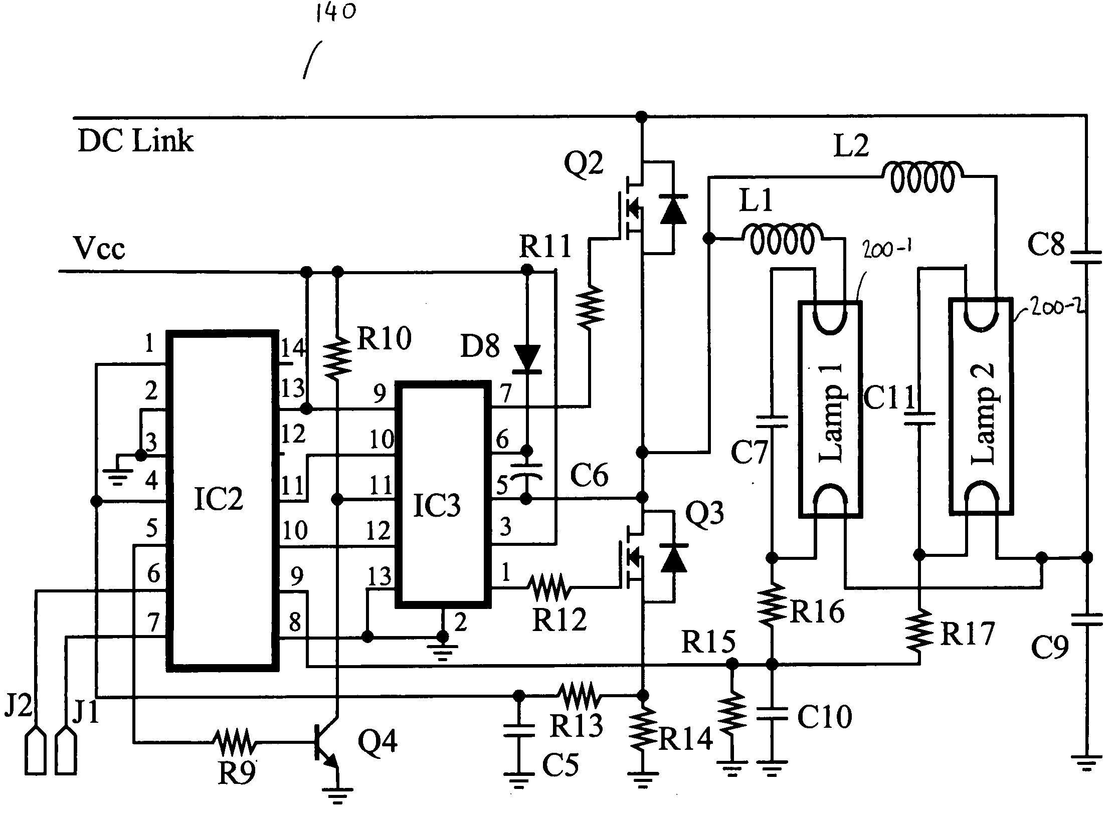
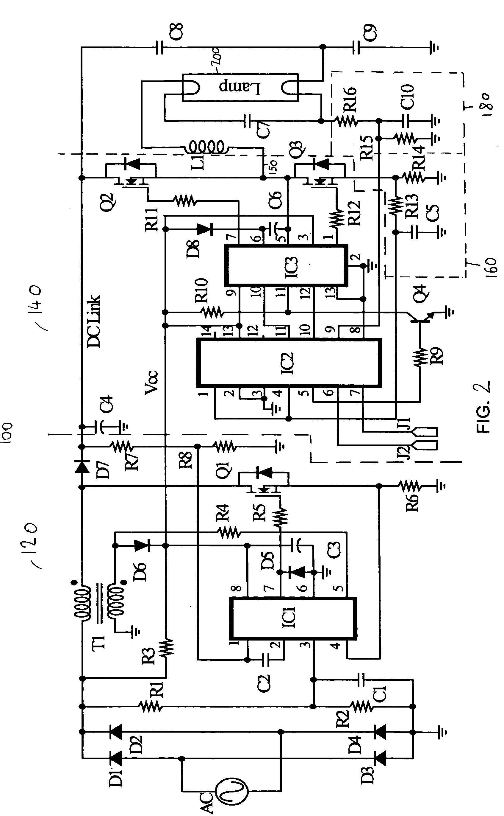
[0009] Briefly and generally, embodiments of the invention include a lamp control circuit, containing a power factor corrector, coupled to a digitally controlled ballast, which contains power devices. The digitally controlled ballast is capable of powering a fluorescent lamp. The ballast is controlled by a current feedback loop, coupled between the power devices and the digitally controlled ballast, and a voltage feedback loop, coupled between the lamp and the digitally controlled ballast.
[0010] Further embodimen

Problems solved by technology

Ballasts utilizing digital controllers also lack some of the functionalities of regular analog ballasts.
For example, in some described ballasts there are no intelligent pre-heating features.
Among the digital ballasts some designs do not provide short-circuit or load-fault protection.
Some have complex pre-heating circuitry with additional auxiliary windings.
Also, the external communication involves the high voltage line, an undesirable feature.
Further, they do not describe pre-heating features.
These circuits often have both digital and analog aspects, thus they are not fully digitally controlled.

Method used


Image

  • Full digital dimming ballast for a fluorescent lamp
  • Full digital dimming ballast for a fluorescent lamp
  • Full digital dimming ballast for a fluorescent lamp

Examples


Embodiment Construction

[0020] Embodiments of the present invention and their advantages are best understood by referring to FIGS. 1-8 of the drawings. Like numerals are used for like and corresponding parts of the various drawings.

[0021]FIG. 1 illustrates a lamp-control circuit 100 with a digital ballast according to an embodiment of the invention. Light control circuit 100 includes a power factor correction circuit 120, coupled to a digital ballast 140. Digital ballast 140 generates a digitally controlled output voltage through an output terminal 150. The output at output terminal 150 is sensed by a current feedback loop 160 and a voltage feedback loop 180. Feedback loops 160 and 180 are coupled back to digital ballast 140.

[0022] Functions of power factor correction circuit 120 include providing an AC input voltage and current essentially in phase with each other. Digital ballast 140 may include a digital controller, microprocessor, or microcomputer. The digital controller is configured to receive feed...


PUM


Abstract

A lamp control circuit is described, containing a power factor corrector, coupled to it a digitally controlled ballast, having power devices. The digitally controlled ballast is capable of powering a lamp. The ballast is controlled by a current feedback loop, coupled between the power devices and the digitally controlled ballast, and a voltage feedback loop, coupled between the lamp and the digitally controlled ballast. Further, a method of operating a lamp-control circuit is presented, the circuit containing a digital controller, an output stage, a current feedback loop, and a voltage feedback loop. In operation the digital controller receives a current feedback signal or a voltage feedback signal from the output stage and the lamp. In response to the received signal the digital controller generates a digital control signal and powers a lamp through the output stage according to the generated digital control signal.

Description

FIELD OF INVENTION [0001] The invention generally relates to a ballast for circuits powering fluorescent and high intensity discharge lamps, and in particular to a digital ballast with voltage and current feedback loops. BACKGROUND OF THE INVENTION [0002] Ballasts are circuits used to drive gas discharge lamps, such as fluorescent lamps. Ballasts adjust the lamp current by adjusting the driving frequency. The driving frequency can be adjusted by using analog voltage-to-frequency converters. [0003] Analog ballasts have a large number of external capacitors and resistors to control various parameters, such as a pre-heating time, soft-start time, minimum and maximum driving frequencies, and running frequencies. [0004] Some ballast circuits lower the number of external capacitors and resistors by including digital controllers. Some digital controllers are capable of identifying the type of the driven lamp. Other circuits use the digital controllers to communicate remotely with an extern...

Claims


Application Information

Patent Timeline
IPC IPC(8): H05B41/282H05B41/392
CPCH05B41/2828Y10S315/04Y02B20/186H05B41/392Y02B20/00H05B41/24H05B41/28H05B41/282H05B41/38
Inventor OH, IN-HWAN
Owner SEMICON COMPONENTS IND LLC
Learn More