Feeding device for sheet material and image recording apparatus for recording an image thereon

Inactive Publication Date: 2005-07-21
FUJIFILM CORP +1
View PDF8 Cites 21 Cited by
  • Summary
  • Abstract
  • Description
  • Claims
  • Application Information

AI Technical Summary

Benefits of technology

[0008] In view of the foregoing, it is a primary object of the present invention to provide a feeding device in which a skew of a sheet material is quickly and accurately corrected even if the sheet material has stiffness.
[0010] In order to achieve the above and other objects, the feeding device according to the present invention comprises a carrier for carrying a sheet material, and an abutting member disposed at a downstream side of the carrier in a carrying direction of the sheet material. After an anterior end of the sheet material has butted against the abutting member, the sheet material is further carried to form a deflection portion thereof between the carrier and the abutting member. The feeding device further comprises a pressing mechanism for pushing the deflection portion of the sheet material. The pressing mechanism presses the entire anterior end of the sheet material against the abutting member to correct a skew of the sheet material. In a preferred embodiment, the abutting member is a feed roller pair for nipping and feeding the sheet material, and the anterior end of the sheet material butts against the feed roller pair of a stop state. The carrier and the feed roller pair are disposed at a curved passage of the sheet material. A carrying guide for guiding the sheet material to the feed roller pair is used to push the deflection portion of the sheet material. The carrying guide is formed with ribs for reducing a contact area of the carrying guide and the sheet material.
[0012] The image recording apparatus according to the present invention comprises a carrier for carrying a recording material, and an abutting member disposed at a downstream side of the carrier in a carrying direction of the recording material. After an anterior end of the recording material has butted against the abutting member, the recording material is further carried to form a deflection portion thereof between the carrier and the abutting member. The image recording apparatus further comprises a pressing mechanism for pushing the deflection portion of the recording material. The pressing mechanism presses the entire anterior end of the recording material against the abutting member to correct a skew of the recording material. In a preferred embodiment, the abutting member is a feed roller pair for nipping and feeding the recording material, and the anterior end of the recording material butts against the feed roller pair of a stop state. The carrier and the feed roller pair are disposed at a curved passage of the recording material. A carrying guide for guiding the recording material to the feed roller pair is used to push the deflection portion of the recording material. The carrying guide is formed with ribs for reducing a contact area of the carrying guide and the recording material.
[0014] According to the present invention, it is possible to quickly and accurately correct the skew of the sheet material and the recording material, even if these materials have stiffness. As a result, processing ability of unit time is improved.

Problems solved by technology

However, the photosensitive material of the cut-sheet shape often inclines while carried.
This means the photosensitive material is often in a skew state.
Thus, quality of the photo print remarkably deteriorates.
However, the photographic paper has stiffness.
Thus, it takes time for correcting the skew.
As a result, processing ability of unit time deteriorates.
Accordingly, there arises a problem in that it is unfavorable to adopt this kind of the photographic printer relative to a minilab apparatus and so forth requiring high processing ability.

Method used


Image

  • Feeding device for sheet material and image recording apparatus for recording an image thereon
  • Feeding device for sheet material and image recording apparatus for recording an image thereon
  • Feeding device for sheet material and image recording apparatus for recording an image thereon

Examples


Embodiment Construction

)

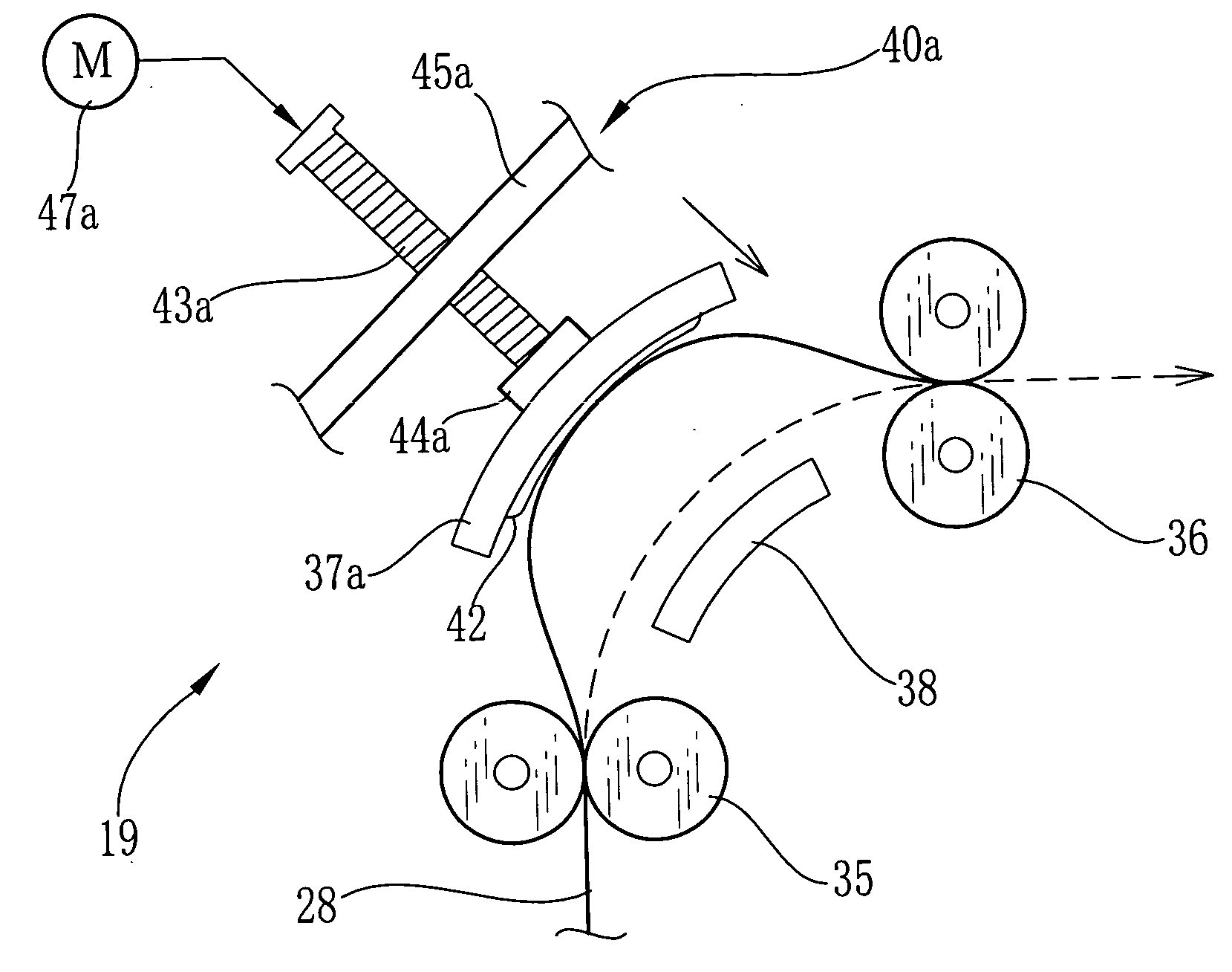
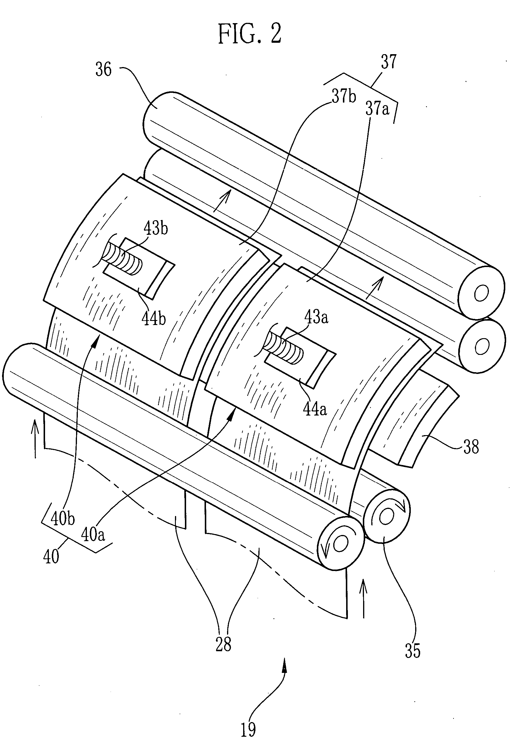
[0024]FIG. 1 is a schematic illustration showing a photographic printer 10 using a feeding device according to the present invention. The photographic printer 10 carries photosensitive materials of a cut-sheet shape in two rows. The photosensitive materials of two rows are simultaneously exposed and are outputted as photo prints. Such as shown in FIG. 1, the photographic printer 10 is constituted of magazines 12 and 13, cutters 15 and 16, a back-printing unit 18, a skew correcting unit 19, an exposing unit 21, a processing unit 22, and so forth.

[0025] The magazines 12 and 13 are disposed at predetermined positions in the photographic printer 10 to respectively contain a recording-paper roll 25 formed by winding a strip-shaped photosensitive recording paper 24 in a roll form. The photosensitive recording paper 24 is regarded as a photosensitive material. A roller pair 27 is disposed near a paper mouth of the respective magazines 12 and 13. Upon rotating the roller pair 27 by a moto...


PUM


Abstract

A photographic printer carries paper sheets in two rows. A skew correcting unit is disposed at a passage of the paper sheets. The skew correcting unit comprises a pre-resist roller pair, a resist roller pair, carrying guides, and pressing mechanisms for moving the carrying guides in an approaching direction to the paper sheet and in a separating direction there from. When correcting the skew of the paper sheet, the pressing mechanism is actuated to move the carrying guide toward a deflection portion of the deflected paper sheet. In virtue of this, an anterior end of the paper sheet is pressed against the resist roller pair. Even if the paper sheet has stiffness, the skew thereof is quickly and accurately corrected.

Description

BACKGROUND OF THE INVENTION [0001] 1. Field of the Invention [0002] The present invention relates to a feeding device for feeding a sheet material and for correcting a skew thereof, and further relates to an image recording apparatus for recording an image on the sheet material (recording material) of which the skew is corrected by the feeding device. [0003] 2. Description of the Related Art [0004] For example, in a photographic printer, feed roller pairs disposed at a passage nip a photosensitive material having a cut-sheet shape to feed it in a sub-scanning direction. While the photosensitive material is fed, recording light is scanned in a scanning direction perpendicular to the sub-scanning direction to record an image by means of scanning exposure. In many photographic printers, the photosensitive materials are carried in parallel and are simultaneously exposed in the scanning direction for the purpose of improving processing ability (amount) of unit time. [0005] In order to ob...

Claims


Application Information

Patent Timeline
IPC IPC(8): B65H5/36B65H5/06B65H9/06B65H9/10B65H9/14
CPCB65H9/103B65H9/06
Inventor KONAGAYA, TATSUYA
Owner FUJIFILM CORP
Why Eureka
Try Eureka