
Device for casting of metal

a technology of metal casting and metal parts, applied in the direction of metal casting devices, continuous or semi-continuous casting devices, etc., can solve the problems of inefficient current distribution, achieve high inward directed forces, reduce induced power losses, and improve efficiency

Inactive Publication Date: 2005-07-21
ABB (SCHWEIZ) AG
View PDF5 Cites 0 Cited by
  • Summary
  • Abstract
  • Description
  • Claims
  • Application Information

AI Technical Summary

Benefits of technology

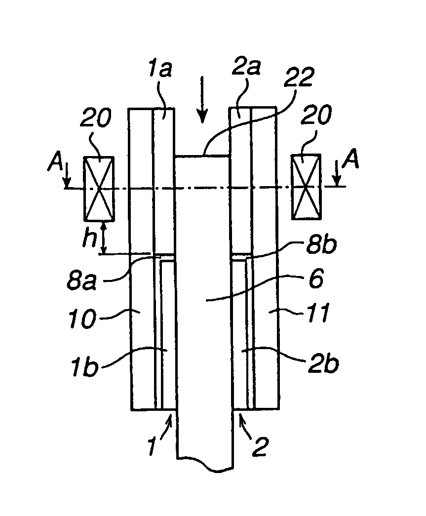
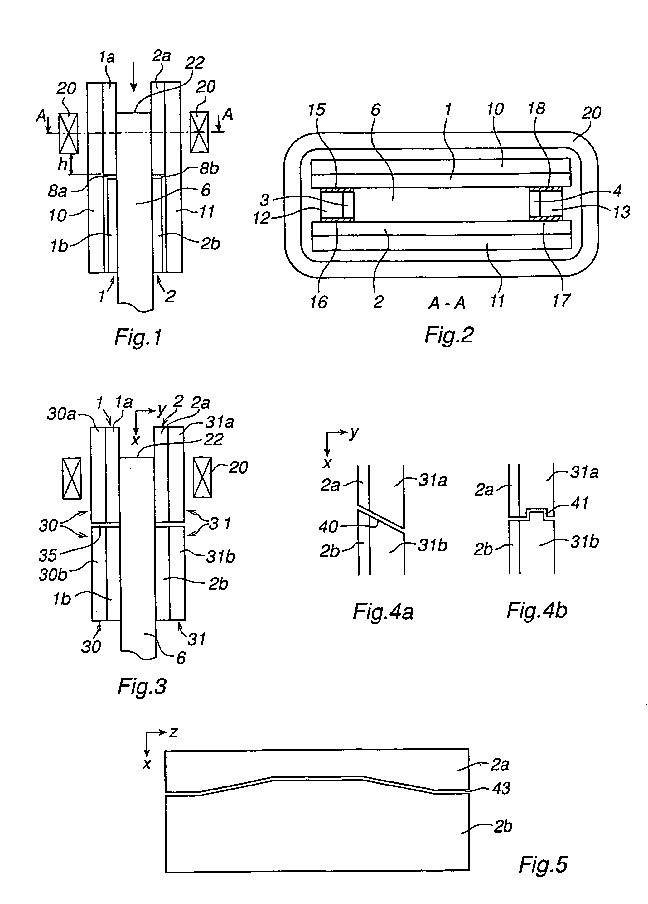
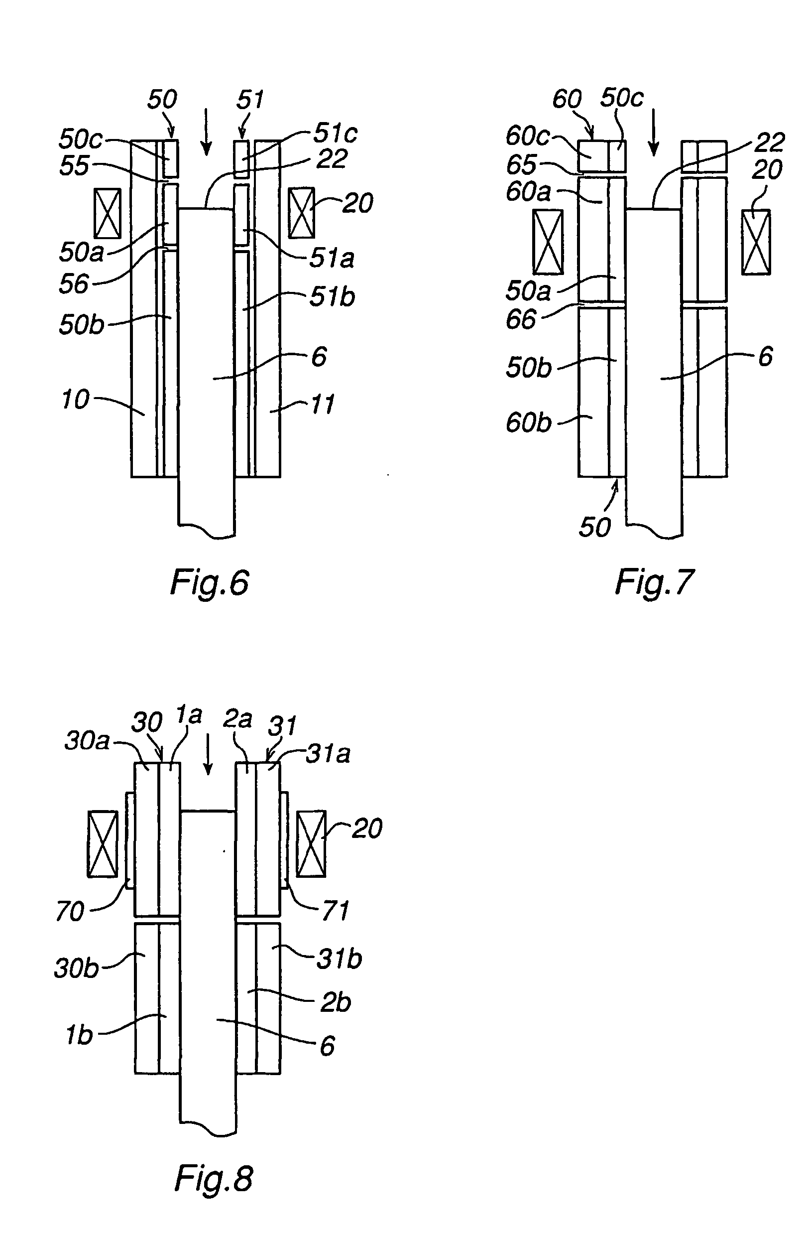
[0012] By dividing the mould, vertically, into at least two parts which are electrically insulated from each other, and arranging the inductive coil close to the one of the mould parts, the propagation of the induced current in the vertical direction on the inside of the mould can be limited to a region around the meniscus, hence reducing the induced power losses. An improvement of the efficiency is attained even when dividing one or a few of the mould elements. One advantage of the present invention is that the electromagnetic pressure remains the same irrespective of the length of the mould.
[0013] According to a preferred embodiment of the invention, the first and second mould element parts are arranged spaced from each other, so that a gap is formed between them, and that the gap is arranged substantially across the casting direction. The mould element is divided by a gap preventing the induced currents from reaching the lower part of the mould element. The gap is advantageously filled with some insulating material, but it may also be filled with air.
[0014] According to another preferred embodiment of the invention, the gap is arranged at a distance from the lower edge of the coil that is smaller than 15 cm. With this arrangement, and provided that the coil is arranged essentially on a level with the meniscus, a concentrated magnetic field, and hence high inwardly directed forces, are exerted on the melt where it is really needed, that is, in the vicinity of the meniscus.
[0015] According to one embodiment of the invention, the divided mould element constitutes at least one side in the casting mould, and the gap is arranged such that the position of the gap in relation to the coil varies along the side of the mould. Instead of having a purely horizontal gap, the position of the gap may be allowed to vary in the vertical direction. In this way, it is possible, at least to a certain extent, to control the distribution of the electromagnetic pressure on the melt along the sides of the mould.
[0016] According to one embodiment of the invention, the gap has an irregular shape, in a section across its longitudinal axis, to bring about a locking in the lateral direction of the first and the second mould element parts against each other. According to a further embodiment of the invention, the gap is arranged, in a section across its longitudinal axis, to be inclined in relation to a plane across the casting direction. One of the tasks of the mould is to retain the cast strand and hence the mould elements are sometimes subjected to large outwardly-directed forces. To prevent the mould element parts from sliding apart, the gap is advantageously formed, in the cross section across the thickness of the mould, with an oblique or irregular shape, or formed with slots to lock the mould element parts to each other.
[0017] According to a further embodiment of the invention, the mould comprises four mould elements in the form of mould plates, two of the mould plates constituting the long sides of the casting mould and the other two mould plates constituting the short sides of the casting mould, and at least the two mould plates that constitute the long sides of the casting mould are divided into said first and second mould element parts. Preferably, the two mould plates that constitute the short sides of the casting mould each consist of one coherent part. Dividing only the long sides of the mould, while leaving the two short sides undivided, has the advantage that the mould manages the above-mentioned outwardly-directed forces in a better way when two sides are undivided while at the same time the improvement of the efficiency becomes almost as high as when all the sides are divided.

Problems solved by technology

Such a distribution of the current becomes inefficient for two reasons: first, because only the electromagnetic pressure in the region nearest below the meniscus can be utilized, and, second, because the electromagnetic pressure is inversely proportional to the propagation of the current in the vertical direction.

Method used


Image

  • Device for casting of metal
  • Device for casting of metal
  • Device for casting of metal

Examples


Embodiment Construction

[0030] A mould for continuous casting is open at both ends in the casting direction and comprises means for ensuring that the formed cast strand continuously leaves the mould. The mould is continuously supplied with a flow of hot molten metal.

[0031] While the melt passes through the mould, it is cooled and solidifies at least partly, whereby a cast strand is formed.

[0032]FIGS. 1 and 2 show a device for continuous casting of metal. The device comprises a mould, which comprises a number of mould elements 1, 2, 3 and 4 which together form a casting mould arranged to receive a liquid metal 6. The mould elements 1-4 are plate-formed and will be designated mould plates in the following. A mould plate is usually made of copper or a copper-based alloy, which may be provided with a coating on the inner surface which faces the melt during operation. The mould plates 1 and 2 also face each other and constitute short sides in the casting mould. Further, the mould plates exhibit a high thermal...


PUM

PropertyMeasurementUnit
distanceaaaaaaaaaa
frequencyaaaaaaaaaa
frequenciesaaaaaaaaaa

Abstract

A device for continuous or semi-continuous casting of metal comprising a mould having a number of mould elements (1, 2) which together form a mould adapted for receiving a liquid metal (6), a mould supporting structure (30, 31) surrounding the mould and mechanically supporting it, and an induction coil (20) arranged close to the mould for reducing the contact pressure between the melt and the mould. At least one of the mould elements is divided into at least a first (1a, 2a) and a second (1b, 2b) part arranged so that they are electrically insulated from each other, the first mould element part being arranged before the second mould element part relative to the casting direction and said induction coil is arranged close to the first mould element part (1a, 2a).

Description

TECHNICAL FIELD [0001] The present invention relates to a device for continuous or semi-continuous casting of metal, comprising a mould with a number of mould elements which together form a casting mould adapted to receive a liquid metal, a mould supporting structure that surrounds the mould and mechanically supports it, and an induction coil arranged adjacent to the mould to reduce the contact pressure between the melt and the mould. The device is used to advantage in continuous casting of metal or metal alloys to form an elongated casting, a so-called cast strand. BACKGROUND ART [0002] In continuous or semi-continuous casting of metals and metal alloys, a hot melt is supplied to a chilled mould intended for continuous casting, that is, a mould that is open in both ends in the casting direction. The mould is normally water-cooled and surrounded and supported by a supporting structure. Usually, the supporting structure comprises supporting beams or supporting plates provided with in...

Claims


Application Information

Patent Timeline
Patent Type & Authority Applications(United States)
IPC IPC(8): B22D11/04B22D11/11B22D11/115
CPCB22D11/115
Inventor JACOBSON, NILSSVENSSON, ERIK
Owner ABB (SCHWEIZ) AG
Learn More