
Water-saving flush toilet

Inactive Publication Date: 2005-07-21
CHU HUNGHING
View PDF6 Cites 12 Cited by
  • Summary
  • Abstract
  • Description
  • Claims
  • Application Information

AI Technical Summary

Benefits of technology

[0008] Water-saving flush toilet of the present invention is adapted to a motor or foot-operated flush toilet to avoid or eliminate disease spreading via touching by hand. If it is motorized, the flushing is automated finished once by pressing a button. Said button can be installed on the top of the storage bin or just on the ground. Said motor is suitable to be operated at a 20V for safety reason.
[0009] A water tank is omitted in this present invention and the cost is lowered as well as increasing the space of the cleaning room. Moreover, it can be replaced by a pleasing design storage bin for sanitary accessories to be used conveniently. The filling time of water tank in a traditional flush toilet is generally takes for 1 to 5 minutes, while the flushing time for the present water-saving flush toilet is only 2 seconds without the filling of water tank, which obviously saves time in flushing and water used.
[0011] If it is possible, metal material should be avoided to be used as the parts in the present invention for preventing corrosion that the working life could be improved.

Problems solved by technology

It is a disadvantage in the environmental protection and in the full utilization of water resource.
If there is no water tank, it still is possible to form vacuum in the discharging end of the siphon pipe for the high-pressure water source, but does not work for a low-pressure water source.
That is, the amount of flushing water is not enough to expel all air in the discharging pipe.

Method used


Image

  • Water-saving flush toilet
  • Water-saving flush toilet

Examples


Embodiment Construction

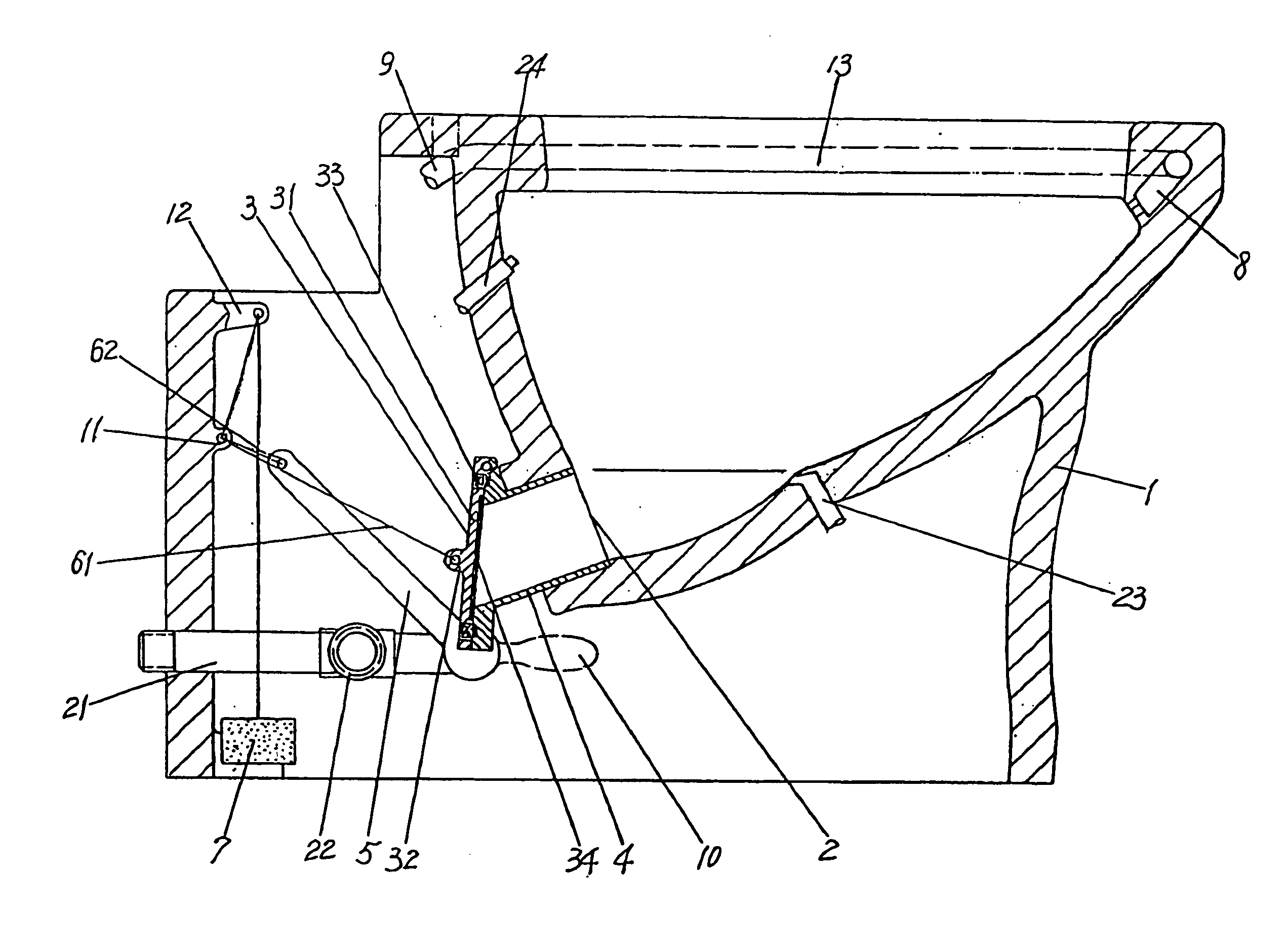
[0013] With reference to FIG. 1, the present invention is a water-saving flush toilet that is a bowl 1 having a seat and a sewage discharge port 2. The bowl 1 is made of resin porcelain clay or porcelain clay. A siphon pipe is omitted at the rear of a sewage discharge pipe of the bowl. A discharge seal valve 3 is arranged at the sewage discharge port 2. The discharge seal valve 3 may be arranged at the front end or rear end of the lower portion of the bowl 1. The sewage discharge port 2 would be out of sight if the discharge seal valve 3 is arranged at the bottom end of the lower portion of the bowl 1, so that it is pleasing and generous in sight.

[0014] The discharge seal valve 3 together with a valve cover 31 are arranged at a valve seat 4. A handle of a water tap 10 at the lower of the bowl is provided with a lever 5. A cord 61 is connected between a handle 32 of the valve cover 31 and a joint 11 of the bowl, said cord 61 is connected to hang a weight 7 via another joint 12 of th...


PUM


Abstract

This present invention relates to a water-saving flush toilet, comprising a bowl having a seat and a sewage discharge port, a siphon pipe is omitted at the rear of a sewage discharge pipe of the bowl. A discharge seal valve is arranged at the sewage discharge port, the discharge seal valve together with a valve cover are arranged at a valve seat. A water tap handle at the lower of the bowl is provided with a lever, a cord is connected between a handle of the valve cover and a joint of the bowl. Said cord is connected to hang a weight via another joint of the bowl. Another end of the lever is connected to another cord and also connected to said weight via said two joints. The upper of the bowl is arranged with a water channel and a sprinkler head, an open of said water channel connected to the water tap at the lower of the bowl via a connecting plastic tube, water pipes are arranged respectively at the upper and the lower of the bowl without any water tank. A water tank is omitted in this present invention and the cost is lowered as well as increasing the space of the cleaning room. The filling time of water tank in a traditional flush toilet is generally takes for 1 to 5 minutes, while the flushing time for the present water-saving flush toilet is only 2 seconds without the filling of water tank, which obviously saves time in flushing and save in water used.

Description

TECHNICAL FIELD [0001] The present invention is related to a sanitary installation, specifically to a water-saving flush toilet. TECHNICAL BACKGROUND [0002] The current flush toilet always uses a siphon pipe to suck / discharge a sewage and to isolate the smell gas. During the discharging, water is firstly filled into the water tank to replenish as a level to the top of the siphon pipe. When discharging a large amount of water to expel the air in a water discharging pipe of the siphon pipe in order to form vacuum such that a pressure difference is produced between both ends. Finally, sewage together with water is discharged into a sewage-discharging pipe by the atmosphere pressure. In regard to the sewage-discharging pipe, the sewage in the flush toilet bowl is sucked into the sewage-discharging pipe and discharged by the sewage-discharging pipe. [0003] The higher the top of the siphon pipe in the water tank, the larger the diameters of sewage discharging pipe, then the more water nee...

Claims


Application Information

Patent Timeline
IPC IPC(8): E03D11/10
CPCE03D11/10
Inventor CHU, HUNGHING
Owner CHU HUNGHING
Learn More