Organic EL display device having organic soluble derivative layer

Inactive Publication Date: 2005-07-14
SAMSUNG DISPLAY CO LTD
View PDF5 Cites 2 Cited by
  • Summary
  • Abstract
  • Description
  • Claims
  • Application Information

AI Technical Summary

Benefits of technology

[0016] Accordingly, it is an object of the present invention to provide an organic EL display device having a high light-emitting efficiency and an improved life span.
[0017] It is another object of the present invention to provide an organic EL display device having an excellent light-emitting layer pattern.
[0019] To achieve the above and other objects of the present invention, there is provided an organic EL display device, comprising: first and second electrodes; a light-emitting layer interposed between the first and second electrodes; an organic soluble derivative layer arranged between the first electrode and the light-emitting layer, wherein the organic soluble derivative layer prevents impurities from being diffused to the light-emitting layer; and a small molecular hole transporting layer between the organic soluble derivative layer and the light-emitting layer.
[0020] There is also provided an organic EL display device, comprising: first and second electrodes; a light-emitting layer arranged between the first and second electrodes; at least one organic soluble derivative layer on the first electrode; and a small molecular hole transporting layer between the light-emitting layer and the organic soluble derivative layer, wherein the organic soluble derivative layer increases an adhesion of the light-emitting layer to the organic EL display device and prevents impurities from being diffused to the light-emitting layer.

Problems solved by technology

In the case of an organic EL display device comprising a polymer, the above-described layers are formed using a spin-coating technique, which places limitations on forming the light-emitting layer thereof.
In addition, water or inorganic and organic impurities affect the light-emitting layer 14, thereby lowering stability and shortening a life span of a resulting device.
The organic EL display device of U.S. Pat. No. 5,247,190 has a disadvantage in that a light-emitting efficiency is low and a life span is short because a work function of the two electrodes is not approximate or identical to a highest occupied molecular orbital (HOMO) value and a lowest unoccupied molecular orbital (LUMO) value of the light-emitting polymer.
However, since the anode electrode has to be made of a transparent conductive material, there are many restrictions to using an anode electrode material.
However, the PEDOT and the PANI are ionic materials which dissolve in water and are high in absorptiveness.
Thus, even though a firing process is performed after the spin coating operation, it is almost impossible to remove the water remaining on a surface thereof.
In addition, the PEDOT and the PANI provide poor adhesion to the light-emitting polymer.
However, a conventional LITI technique shows a bad transfer characteristic.

Method used


Image

  • Organic EL display device having organic soluble derivative layer
  • Organic EL display device having organic soluble derivative layer
  • Organic EL display device having organic soluble derivative layer

Examples


Embodiment Construction

[0033] Reference will now be made in detail to the embodiments of the present invention, examples of which are illustrated in the accompanying drawings, wherein like reference numerals refer to the like elements throughout. The embodiments are described below in order to explain the present invention by referring to the figures.

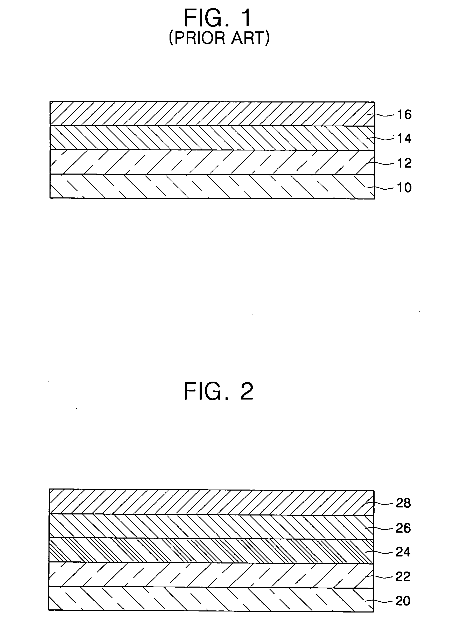
[0034]FIG. 2 shows a cross-sectional view illustrating an organic EL display device according to an embodiment of the present invention. The organic EL display device includes an anode 20, a hole injection layer 22(), an organic soluble derivative layer 22, a small molecular hole transporting layer 24, a light-emitting layer 26, and a cathode electrode 28 which are stacked in sequence.

[0035] The organic soluble derivative layer 24 prevents impurities from being diffused from the hole injection layer 22 to the light-emitting layer 26 without lowering a hole transporting ability, thereby improving a performance characteristic of a resulting device. When the s...


PUM

PropertyMeasurementUnit
Thicknessaaaaaaaaaa
Thicknessaaaaaaaaaa
Solubility (mass)aaaaaaaaaa

Abstract

An organic EL display device includes first and second electrodes, a light-emitting layer interposed between the first and second electrodes, an organic soluble derivative layer arranged between the first electrode and the light-emitting layer, wherein the organic soluble derivative layer prevents impurities from being diffused to the light-emitting layer, and a small molecular hole transporting layer between the organic soluble derivative layer and the light-emitting layer.

Description

CROSS-REFERENCE TO RELATED APPLICATIONS [0001] This application is a continuation-in-part application of U.S. application Ser. No. 10 / 167,651, filed Jun. 13, 2002, which claims the benefit of Korean Patent Application No. 2001-74703 filed on Nov. 28, 2001, both of which are hereby incorporated by reference for all purposes as if fully set forth herein.BACKGROUND OF THE INVENTION [0002] 1. Field of the Invention [0003] The present invention relates to an organic electroluminescent (EL) display device, and more particularly, to an organic EL display device having an organic soluble derivative layer. [0004] 2. Description of the Related Art [0005] An organic EL display device includes an anode, a hole injection layer, a hole transporting layer, a light-emitting layer, an electron transporting layer, an electron injection layer, and a cathode which are sequentially stacked on a substrate. In the case of an organic EL display device comprising a low-molecular material, the above-describe...

Claims


Application Information

Patent Timeline
IPC IPC(8): H01L51/30H01L51/40H01L51/50
CPCH01L51/0013H01L51/5048H01L51/0059H10K71/18H10K85/631H10K50/14
Inventor SUH, MIN-CHULKIM, MU-HYUNKWON, JANG-HYUK
Owner SAMSUNG DISPLAY CO LTD
Why Eureka
Try Eureka