
High temperature power supply

Inactive Publication Date: 2005-07-14
THE BOEING CO +1
View PDF2 Cites 3 Cited by
  • Summary
  • Abstract
  • Description
  • Claims
  • Application Information

AI Technical Summary

Benefits of technology

[0006] It is well known that heat transfer from a body to its surrounding environment by thermal radiation is proportional to T4 where “T” is the body's temperature. Therefore, raising the temperature of the active devices in a power supply increases heat transfer significantly. Prior art silicon semiconductor devices leak current across their junctions at temperatures over 125° C., making them ill suited for applications where the ambient temperature is over approximately 125° C. By using “wide-band gap” semiconductors however, junction leakage current at high ambient temperatures is much less, making it possible to operate a semiconductor power supply in ambient temperatures over 300° C. using relatively small heat sinks.
[0007] The term “band gap” used herein refers to the energy difference between a material's non-conductive state and its conductive state. There is virtually no “band gap” in most metals, but a very large one in an insulator (dielectric). Technically, the “band gap” is the energy it takes to move electrons from the valence band to the conduction band. In most semiconductors, the “band gap” is relatively small. Silicon semiconductors have a band gap of approximately 1.12 eV. As used herein, a “wide band g

Problems solved by technology

Therefore, raising the temperature of the active devices in a power supply increases heat transfer significantly.
Prior art silicon semiconductor devices leak current across their junctions at temperatures over 125° C., making them ill suited for applications where the ambient temperature is over approximately 125° C. By using “wide-band gap” semiconductors however, junction leakage current at high ambient temperatures is much less, making it possible to operate a semiconductor power supply in ambient temperatures over 300° C. using relatively small heat sinks.

Method used


Image

  • High temperature power supply
  • High temperature power supply
  • High temperature power supply

Examples


Embodiment Construction

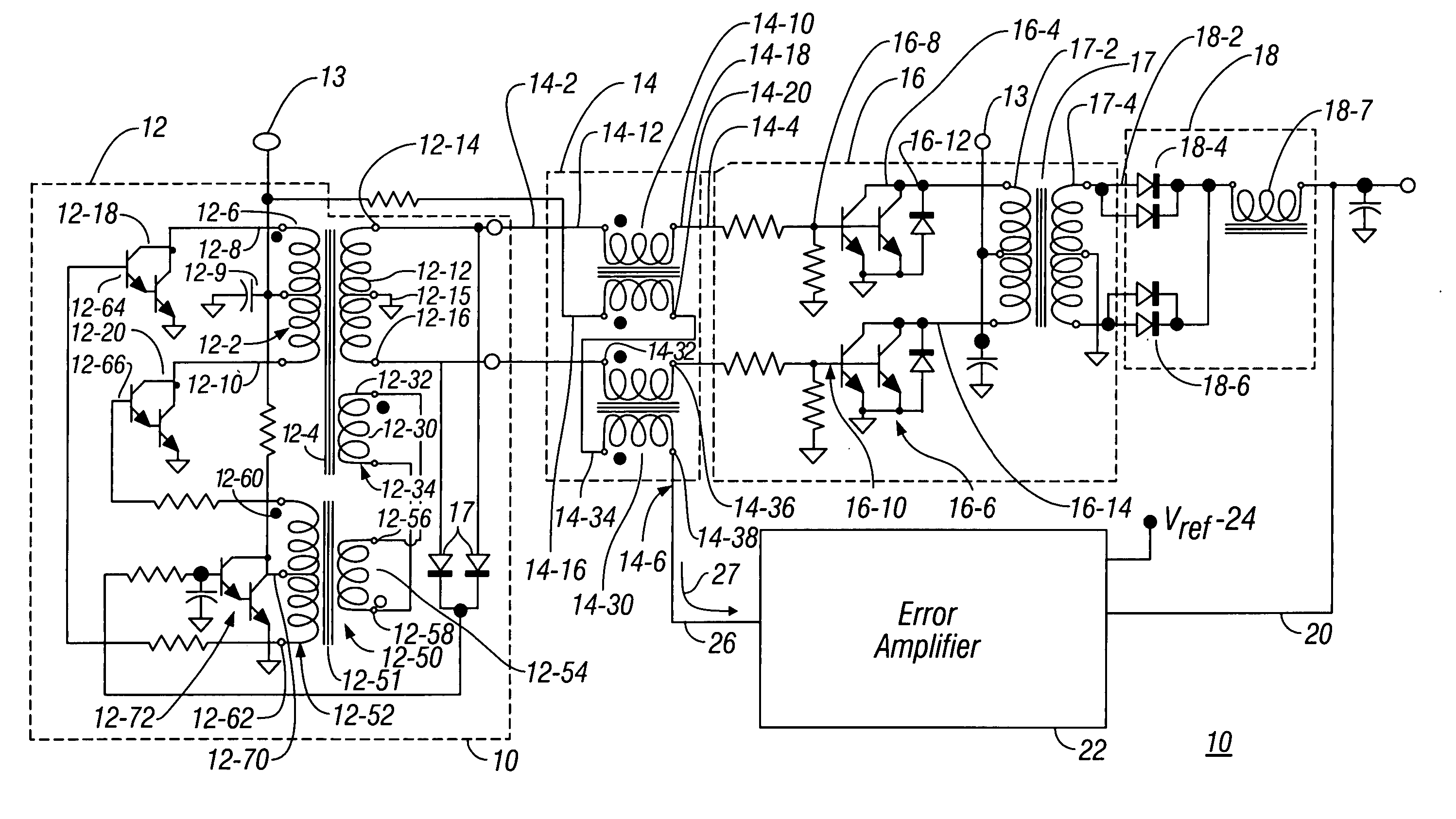
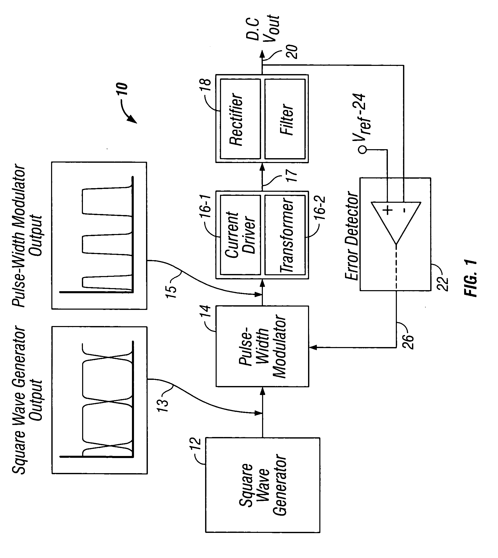
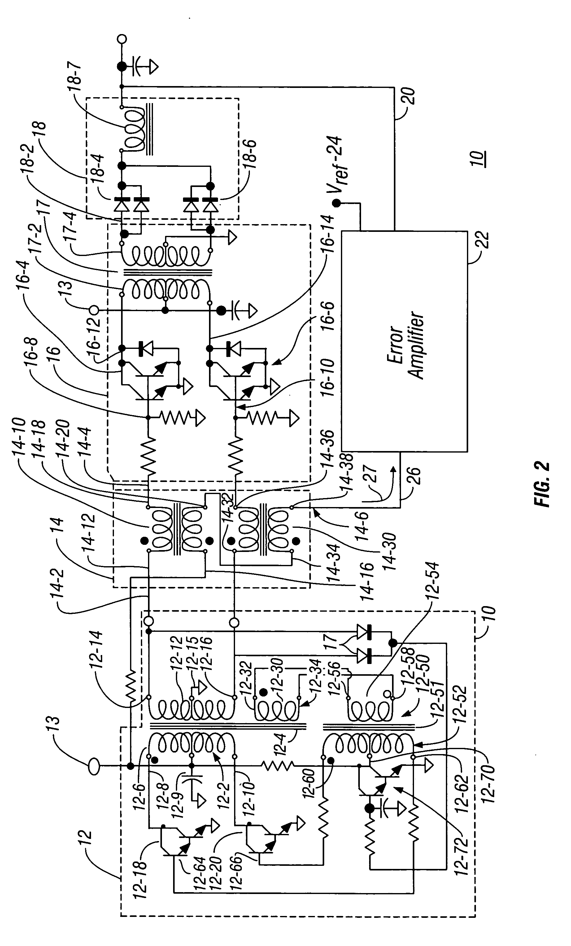
[0011]FIG. 1 is a block diagram of functional elements of the high temperature power supply 10. The square wave generator 12, which is implemented by a Royer circuit and described more fully below, generates a square wave output pulse stream depicted by the waveform 13 shown in FIG. 1. The pulse width modulator 14 allows only a portion of each pulse from the Royer circuit to turn on a current driver 16-1, the output of which drives current through the primary winding of an output transformer 16-2. The output winding of the transformer 16-2 is rectified and filtered 18 to produce a D.C. output voltage 20.

[0012] The output of the pulse with modulator 14 is a stream of pulses, 15 that are output from the Royer circuit 12. Inasmuch as the pulses output from the pulse width modulator 14 will vary according to the load on the power supply and its desired output voltage, the pulse width modulator 14 output signal can be considered a “variable pulse width output” signal. The time duration ...


PUM


Abstract

A high-temperature, regulated power supply uses wide band gap transistors to drive a Royer circuit. Pulses output from the Royer circuit are gated through a pulse width modulator to control the duty cycle of wide band gap transistors that drive an output transformer. The output of the transformer is rectified and filtered to provide the regulated D.C. output voltage. Regulation is accomplished by sampling the output voltage, comparing it to a reference voltage and using the difference between the output voltage and the reference voltage to control the pulse width modulator. High temperature operability is provided by using wide band gap transistors and iron or steel core transformers. This technique also provides a radiation hard assembly.

Description

FIELD OF THE INVENTION [0001] This invention relates to power supplies. More particularly, this invention relates to a lightweight power supply, capable of operating in ambient temperatures as high as 300° C. BACKGROUND OF THE INVENTION [0002] Existing power supplies use well-known silicon semiconductors, which work well at temperatures up to approximately 125° C. but silicon semiconductors are ill suited for applications where ambient temperatures are above 125° C. At temperatures over approximately 125° C., charge carriers in silicon leak across P-N junction. [0003] Even at temperatures below 125° C., silicon semiconductors that require high-power dissipation require a heat sink to dissipate heat in order to protect the devices from being damaged. Heat sinks take up space and add weight. Accordingly, there exists a need for a power converter also known as a regulated power supply that is usable in high temperature environments but which is also operable with minimally-sized heat s...

Claims


Application Information

Patent Timeline
IPC IPC(8): H02M1/08H02M3/335
CPCH02M1/08Y02B70/1483H02M3/335Y02B70/10
Inventor LYNCH, THOMAS H.SOENDKER, ERICH H.HERTEL, THOMAS A.
Owner THE BOEING CO
Learn More