Circuit arrangment for operating light sources

a technology for operating light sources and circuits, applied in the direction of electric variable regulation, process and machine control, instruments, etc., can solve the problems of inability to achieve rated current harmonics, affecting components such as inductors and electronic switches, and affecting the efficiency of circuit arrangemen

Inactive Publication Date: 2005-07-14
PATENT TREUHAND GESELLSCHAFT FUR ELECTRIC GLUEHLAMPEN MBH
View PDF7 Cites 5 Cited by
  • Summary
  • Abstract
  • Description
  • Claims
  • Application Information

AI Technical Summary

Benefits of technology

[0030] One particularly advantageous refinement of the invention is characterized in that an inverter is in the form of a half-bridge inverter. The inverter is connected between a positive and a negative busbar and as a result is supplied with a DC voltage. The inverter provides a radiofrequency AC voltage at an inverter output for operating light sources. The design of the inverter as a half-bridge inverter makes it possible to achieve a particularly high efficiency of the circuit arrangement.
[0031] A further, particularly advantageous refinement of the invention is characterized in that one connection of the light source is connected to the positive or negative busbar via a coupling capacitor. A further reduction of the rated current harmonics and the lamp current crest factor is thus achieved.

Problems solved by technology

This additional loading affects components such as inductors and electronic switches and is caused by excess currents and voltages which are produced in connection with wattless power transport.
However, with a valley fill circuit alone it is not possible to achieve any rated current harmonics which conform to standards.

Method used


Image

  • Circuit arrangment for operating light sources
  • Circuit arrangment for operating light sources

Examples


Embodiment Construction

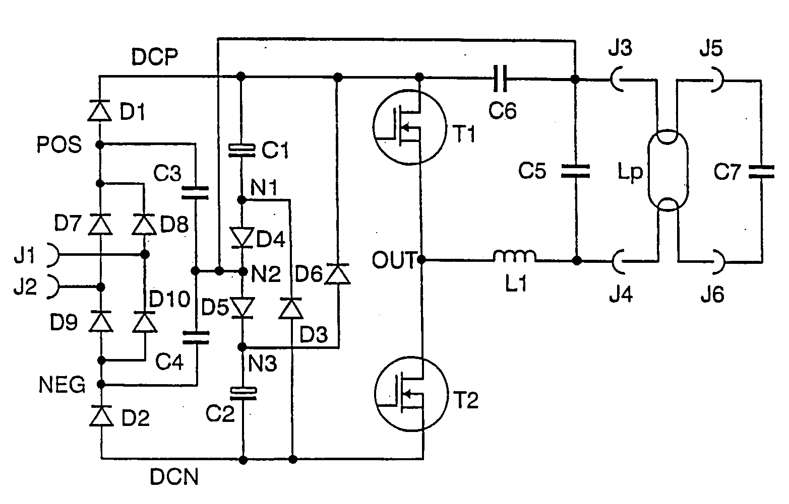
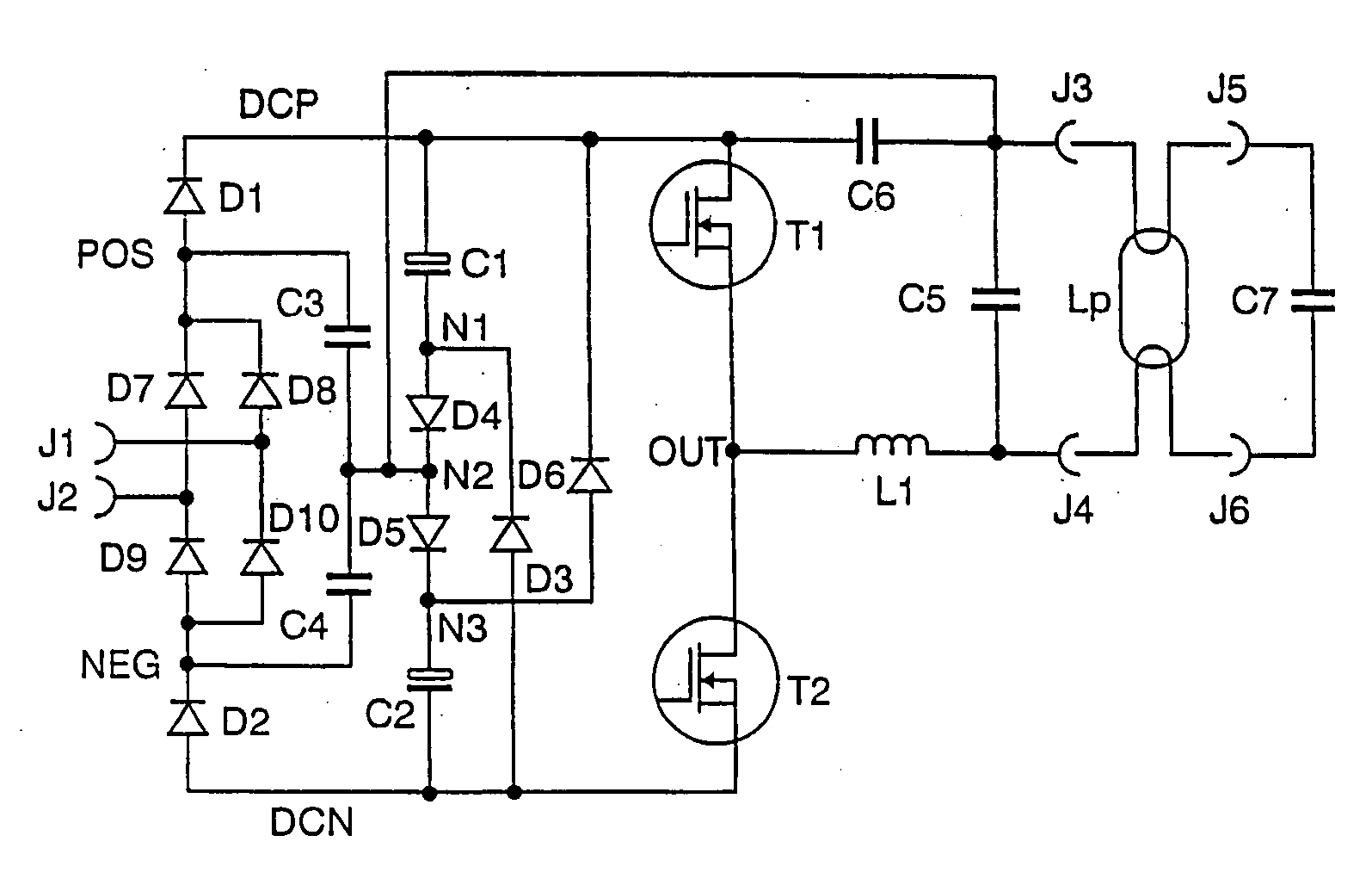
[0034] In the FIGURE, the connections J1 and J2 form the system voltage input. A system voltage can be connected to J1 and J2. J1 and J2 are connected to the input of a rectifier. Means for suppressing radio interference can also be connected upstream of the rectifier.

[0035] In general, the rectifier comprises a known bridge circuit comprising the rectifier diodes D7, D8, D9 and D10 which provides the rectified system voltage at its positive rectifier output POS and at its negative rectifier output NEG. Owing to the charge pump it must be possible for the rectifier diodes to switch at a high frequency. It is also possible to use slow rectifier diodes. In this case, however, in each case a fast diode needs to be connected between the bridge circuit and the respective rectifier output.

[0036] A first diode D1, which is a pump diode, is connected at its anode to the positive rectifier output POS and at its cathode to a positive busbar DCP.

[0037] A second diode D2, which is likewise a...


PUM


Abstract

In a circuit arrangement for operating light sources, inexpensive technologies for power factor correction can be used in combination. Owing to the combination of a dual charge pump and a valley fill circuit it is also possible to adhere to relevant standards for rated current harmonics even at rated powers of over 25 W whilst maintaining low component loading.

Description

[0001] A patent application which relates to a similar circuit arrangement has been filed on the same application date under our reference 2004P00168. FIELD OF THE INVENTION [0002] The invention relates to circuit arrangements for operating light sources. The invention relates in particular to circuit arrangements for supplying power to light sources from a supply system which are suitable for correcting a system-side power factor. The abbreviation PFC will be used below for the term power factor correction. [0003] A feed system voltage has a system frequency. The term “radiofrequency” will be used below for frequencies which are substantially higher than the system frequency. BACKGROUND OF THE INVENTION [0004] The document WO 02 / 47441 (Hu) discloses an abovementioned circuit arrangement. In this document, two PFC technologies are disclosed: a charge pump (“single feedback”) and a so-called valley fill circuit (“double pump”). Here, the charge pump is connected upstream of the valle...

Claims


Application Information

Patent Timeline
Patent Type & Authority Applications(United States)
IPC IPC(8): H05B41/24H02M1/00H02M1/42H05B41/28
CPCH02M1/425Y02B70/126H05B41/28Y02B70/10A45B25/06
Inventor HOO, HENRYLIU, KENSCHMITT, HARALDTWARDZIK, RENE
Owner PATENT TREUHAND GESELLSCHAFT FUR ELECTRIC GLUEHLAMPEN MBH
Why Eureka
Try Eureka