Method for correcting the image data o a camera system

Inactive Publication Date: 2005-07-07
KOENIG & BAUER AG
View PDF13 Cites 24 Cited by
  • Summary
  • Abstract
  • Description
  • Claims
  • Application Information

AI Technical Summary

Benefits of technology

[0010] In the method of the present invention the output signal vectors are multiplied by, preferably, a quadratic correction matrix, and so the image data can be changed in a simple way so that they approach the color perception of the human eye. Multiplication by a correction matrix provides a relatively accurate arrangement of all printing colors in a basically arbitrary color range. Moreover, the conversion by multiplication with a correction matrix can be performed on camera image data in such a simple way that practical and cost effective implementation is possible even for large amounts of image data.
[0012] Advantageously, this method includes calculation of the color correction values for different illumination sources and changes among different illumination sources. At present, the standard light source, known as a D50 is used in printing technology. By predetermining the illumination characteristics of a D50 light source it is possible to match the Rec. 709 color standard by conversion to the D50 standard light, so that the intensities of the non-linear R′, G′, B′ values act as if the object to be investigated were illuminated by a D50 standard light's illumination. A measurement method interactively matches the values of the R′, G′, B′ color range with the CIELAB color range, to adapt the color ranges to each other without a real standard illumination being required. This method has the advantage that in case of a change of the standard light conditions to be expected, the change in illumination can be compensated for immediately by executing the method of the present invention in computer software.
[0014] Next, the approach of the corrected output signal values is compared to the preset nominal vectors for each iteration step in order to be able to decide, on the basis of this comparison, whether the changes of the coefficients of the correction matrix made in this iteration step are to be used or discarded. In the comparison or assessment method of the present invention, the difference value between the corrected output signal value and the nominal vector predetermined for the color field is determined for each color field of the reference color table, and the sum of all these difference values is added together. The change of the correction coefficient of the correction matrix in the last iteration step is then used only if the sum of all difference values in the last iteration step has become smaller. But if the sum of all difference values by changing the coefficient of the correction matrix has become larger in the last iteration step, the change in the coefficients is not used and discarded. By checking the sum of the difference values over all reference colors, it is easily possible that the difference for individual reference colors increases in the course of an iteration step. However, as a whole, minimizing the difference values over all color channels is dependably assured.
[0019] These pixel-specific, color channel-dependent correction factors can for example be experimentally determined in a simple way, in that the observation area of the CCD camera is covered in a homogeneous material, in particular a homogeneous white material, and an output signal vector is determined for each pixel by triggering the camera. The output signal vector having the highest coefficients, and therefore represents the brightest point in the observation area, is then filtered out of all these output signal vectors. But since the observation area is covered by a homogeneous colored material, all pixels should provide output signal vectors which essentially agree identically with each other. Therefore the respective differences are based on color distortions or on a drop in intensity because of the structural type. To compensate for this, correction factors are now selected for each color channel of each individual pixel, which assure that during the recording of the homogeneous colored material all output signal vectors correspond to the output signal vector at the brightest spot in the observation area.

Problems solved by technology

In connection with the known camera systems, a problem occurring during the inspection of colored printed products is that the color data provided by the color cameras often do not correspond to the color sense of the human eye.
Unprocessed image data from these color cameras are unsatisfactory in the areas of color balance, brightness, contrast and reproduction of the color hue when compared to human color perception.
Both optical devices and illumination devices have shortcomings and the spectral sensitivity distribution of CCD cameras exacerbates the color balance problems, brightness problems, contrast problems and color hue problems.
The sensitivity distribution of the cameras used does not always agree with the sensitivity distribution of the human eye, and so the image data provided by the color camera makes a false visual impression during later processing, such as when viewed on a video display monitor.

Method used


Image

  • Method for correcting the image data o a camera system
  • Method for correcting the image data o a camera system

Examples


Embodiment Construction

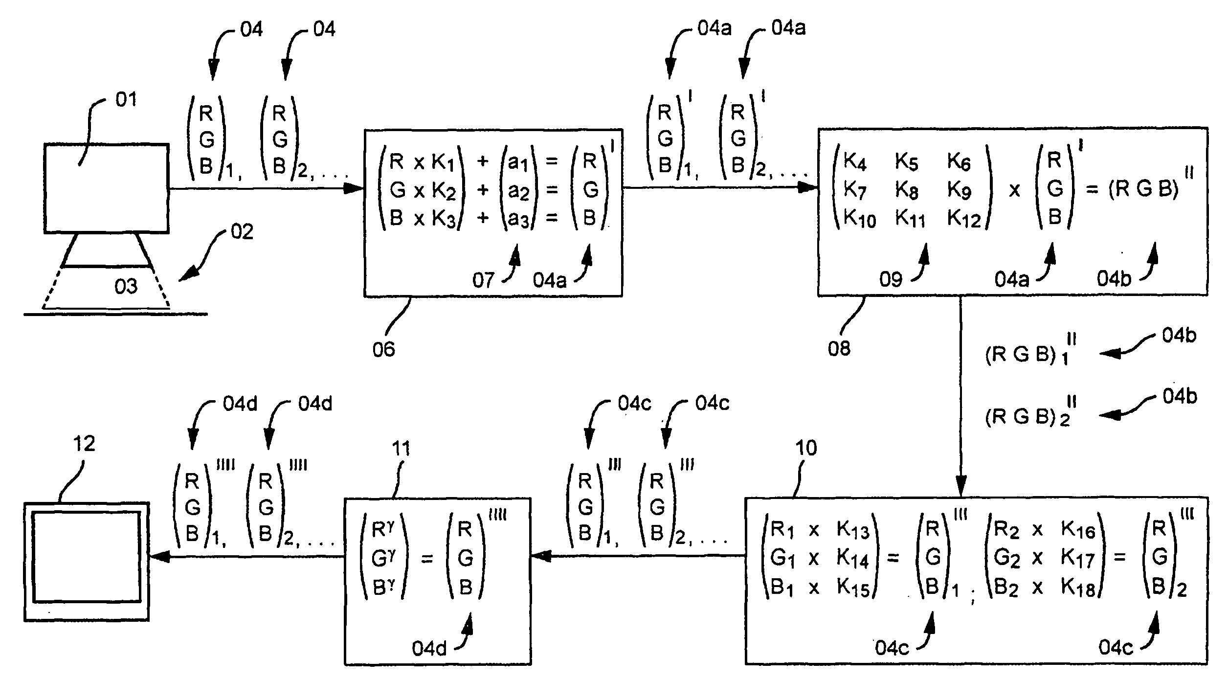
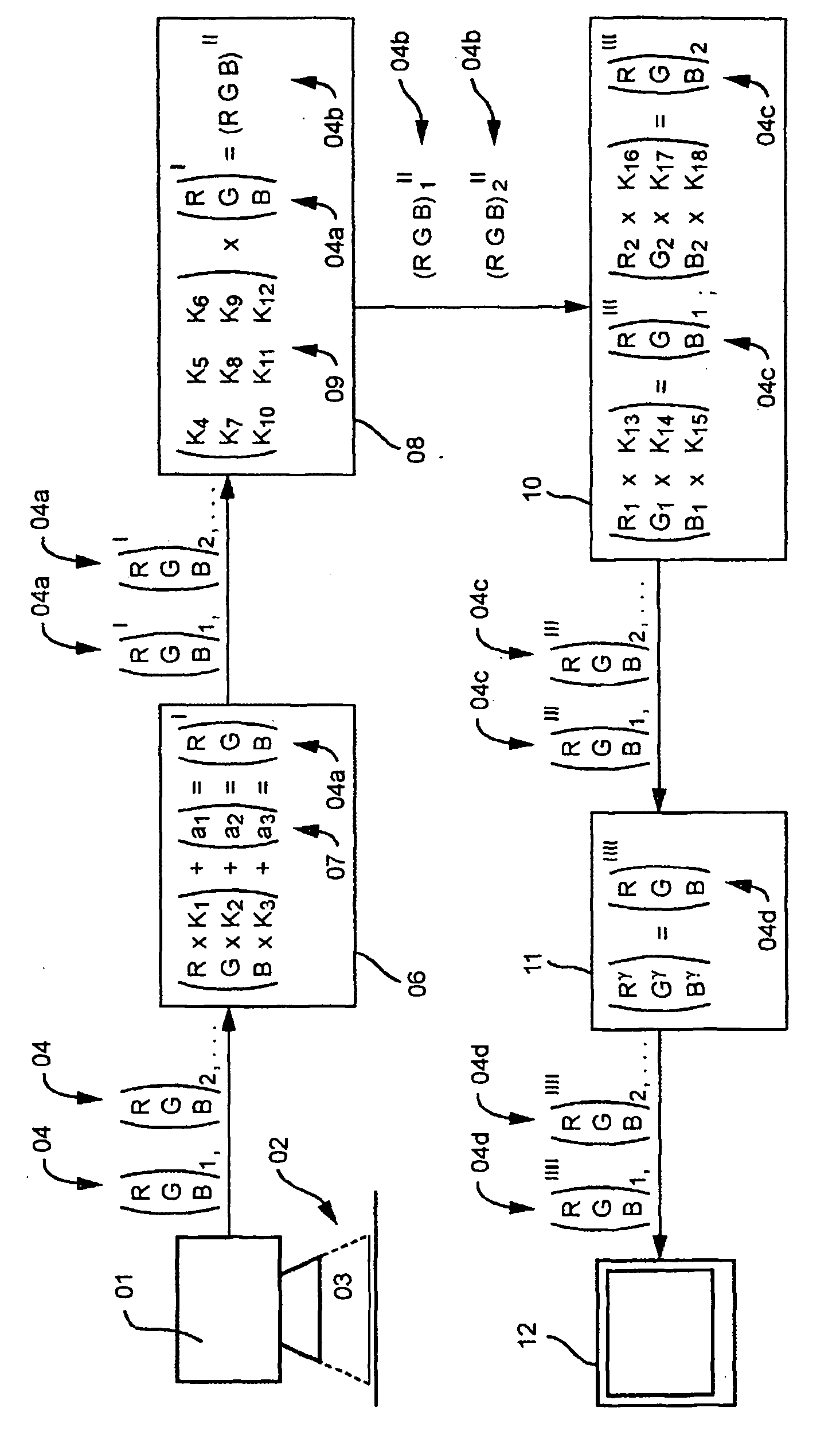
[0026] Referring to FIG. 1, a printed product 03, is arranged in an observation area 02 and is imprinted in colors. An image of printed product 03 is recorded with a color camera 01, preferably a CCD camera. A CCD chip is provided in the color camera 01, which converts the image information in the observation area 02 into electronic image data. In the course of this conversion, an output signal vector 04 is generated by each light-sensitive pixel of the CCD chip. A number of output signal vectors 04 corresponding to the number of pixels on the CCD chip are made available by the color camera 01 for further processing.

[0027] Each output signal vector 04 preferably includes three coefficients R, G and B. The coefficients R, G and B correspond to the color values of the three color channels red, green and blue, wherein the color of the printed product 03 at the position in the observation area which was recorded by the corresponding pixel, corresponds to the mixture of the three color ...


PUM


Abstract

The image data of a camera system is corrected. The camera system includes a color camera which supplies three output signals to three separate color channels, in the form of output signal vectors. The output signal vectors, the coefficients of which represent the output signals supplied by the color camera to the three color channels in a specific position lying in the range of observation, are multiplied by a correction matrix, particularly a square one. The corrected output signal vectors are then processed further in the camera system.

Description

CROSS-REFERENCE TO RELATED APPLICATIONS [0001] This application is the U.S. National Phase under 35 USC 371 of PCT / DE 03 / 00570, filed Dec. 12, 2003; published as WO 03 / 073748 A2 on Sep. 4, 2003 and claiming priority to DE 102 08 285.5 filed Feb. 26, 2002, the disclosures of which are expressly incorporated herein by reference.FIELD OF THE INVENTION [0002] The present invention is directed to a method for evaluating and correcting the image data of a color camera system that is particularly well suited for inspecting color printed products. BACKGROUND OF THE INVENTION [0003] Camera systems are widely used for various applications, particularly in the printing industry. For example, camera systems can be used for registration measuring systems, inspection systems or web monitoring systems. In many cases digital image sensors such as CCD cameras are employed as color cameras, whose light-sensitive pixels provide three output signals corresponding to the colors recorded in the observati...

Claims


Application Information

Patent Timeline
IPC IPC(8): H04N1/60
CPCH04N1/6033H04N1/60
Inventor LOHWEG, VOLKERWILLEKE, HARALD HEINRICH
Owner KOENIG & BAUER AG
Why Eureka
Try Eureka