
Golf swing diagnosis system

a golf swing and diagnosis system technology, applied in closed circuit television systems, gymnastics exercises, instruments, etc., can solve problems such as erroneous extraction of golfer image of a different position, inability of apparatus to provide useful information for improving golfer's swing form, and inability to correct swing form at impact tim

Inactive Publication Date: 2005-06-30
SHIRAI YOSHIAKI +2
View PDF4 Cites 50 Cited by
  • Summary
  • Abstract
  • Description
  • Claims
  • Application Information

AI Technical Summary

Benefits of technology

[0010] The present invention has been made in view of the above-described problems. Therefore it is an object of the present invention to provide a system of capable of precisely extracting still images of a swing position effective for diagnosing a golf swing from a moving image of a photographed golf swing.
[0018] In the above-described construction, to detect the position of each of the colored marks, whether a region falls within the color range is judged not in the entire screen but only in the search range. Therefore when the still image includes a color proximate to that of the colored mark, it is possible to eliminate the color, prevent an erroneous recognition, and shorten a computing period of time.
[0019] Differential processing is executed between the pixel within the search range of the still image and the background image to eliminate the background image. Thereby even if the background image includes the color proximate to that of the colored mark, it is possible to eliminate the color and prevent the erroneous recognition to a higher extent. The erroneous recognition can be prevented by carrying out a method in which the size of the area of the colored mark and the shape of the colored mark are considered.
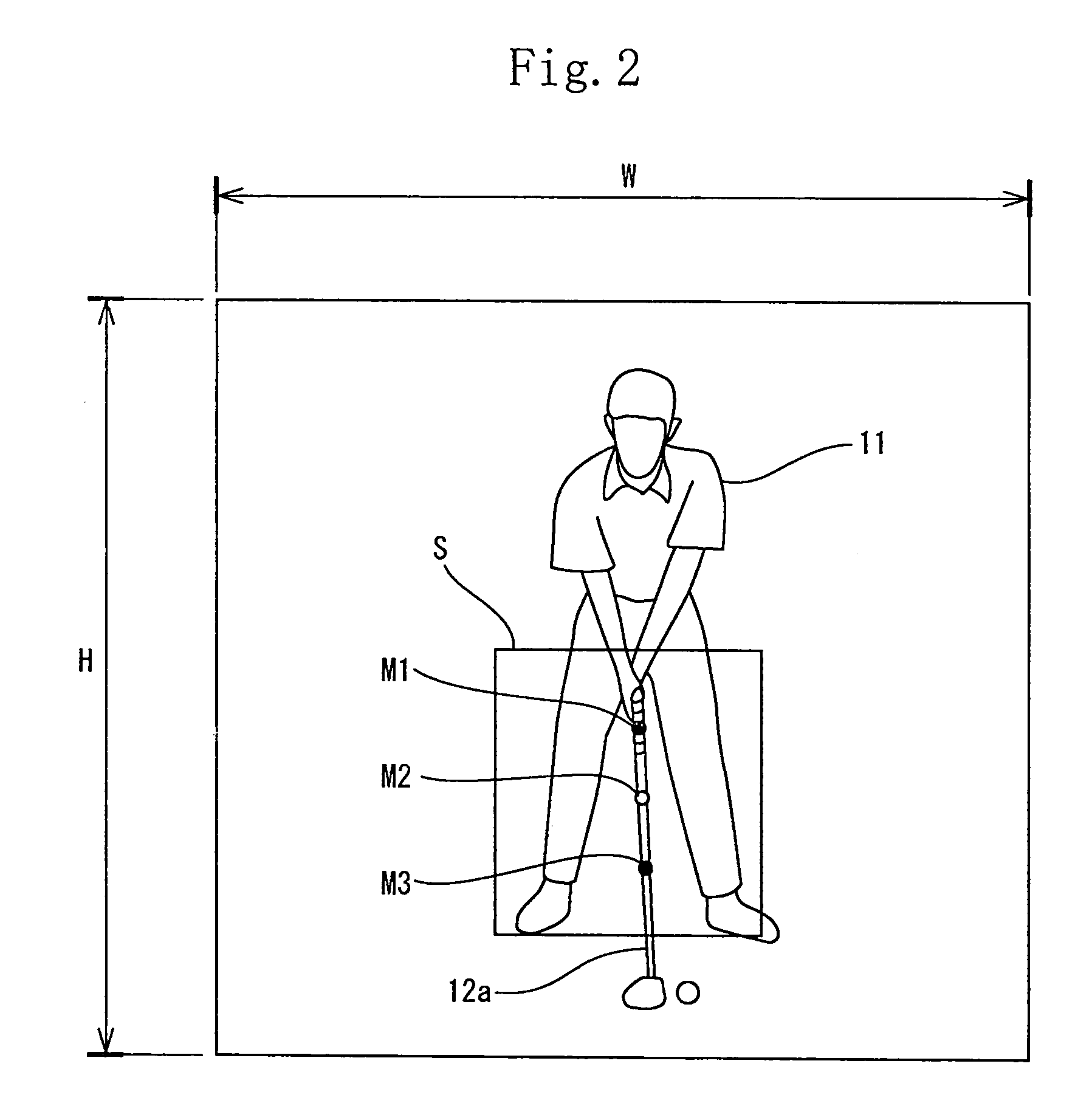
[0026] The operation extraction means executes differential processing of the still image by using a background image in which a golfer is not photographed to obtain a golfer's silhouette; extracts a contour of the silhouette; regards a pixel which makes a curvature of the contour extreme as an unskillful arm side shoulder; computes a position of the grip from a positional relationship between two of the colored marks; stores at least one part of the still image in a range from the shoulder at the unskillful arm side to the grip as a template; and extracts a movement of a golfer's unskillful arm by executing template matching processing for a still image during a take-back swing. The image extraction means regards a frame of the still image in which the template has become horizontal as an image in which the unskillful arm is horizontal in the take-back swing, based on data obtained by the operation extraction means, thus extracting the still image as a check-point image. It is possible to execute the matching processing at the template angle in which starts the template matching processing without extracting silhouette from the angle as prescribed and memorized.
[0052] This construction reliably prevents the golfer's skin color from being erroneously recognized as the color of the colored mark.

Problems solved by technology

However, these apparatuses are incapable of providing information useful for improving the golfer's swing form.
This is because the swing form cannot be corrected at the impact time, if the golfer has an improper swing in the neighborhood of the impact time.
Thus there is a high possibility that an image of a different position is erroneously extracted for a golfer.
Considering that golfers' swing tempos are quite different from each other, it is impossible to extract an image of the same swing position (swing posture) for a plurality of golfers.
Thus even if a golfer intends to improve her / his swing form at the time when the golf club shaft is horizontal by comparing her / his swing form with a swing form of a high-class player or that of a professional player, there is no guarantee that the extracted image of her / his swing form is the image at the time when the golf club shaft is horizontal.
Therefore it is impossible to compare her / his swing form with that of the high-class player or that of the professional player in the same swing position (posture).

Method used


Image

  • Golf swing diagnosis system
  • Golf swing diagnosis system
  • Golf swing diagnosis system

Examples


Embodiment Construction

[0073] The embodiments of the present invention will be described below with reference to drawings.

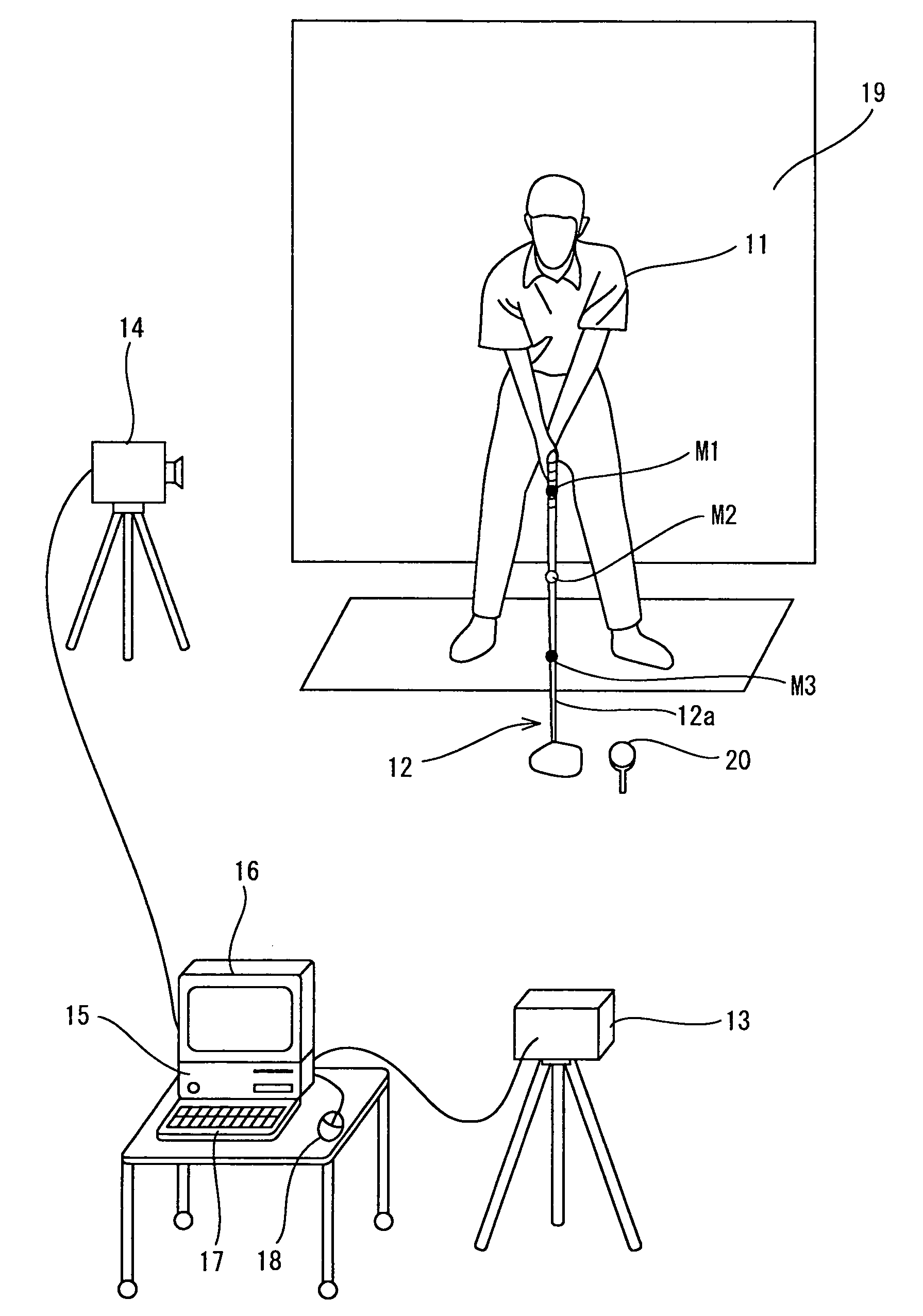
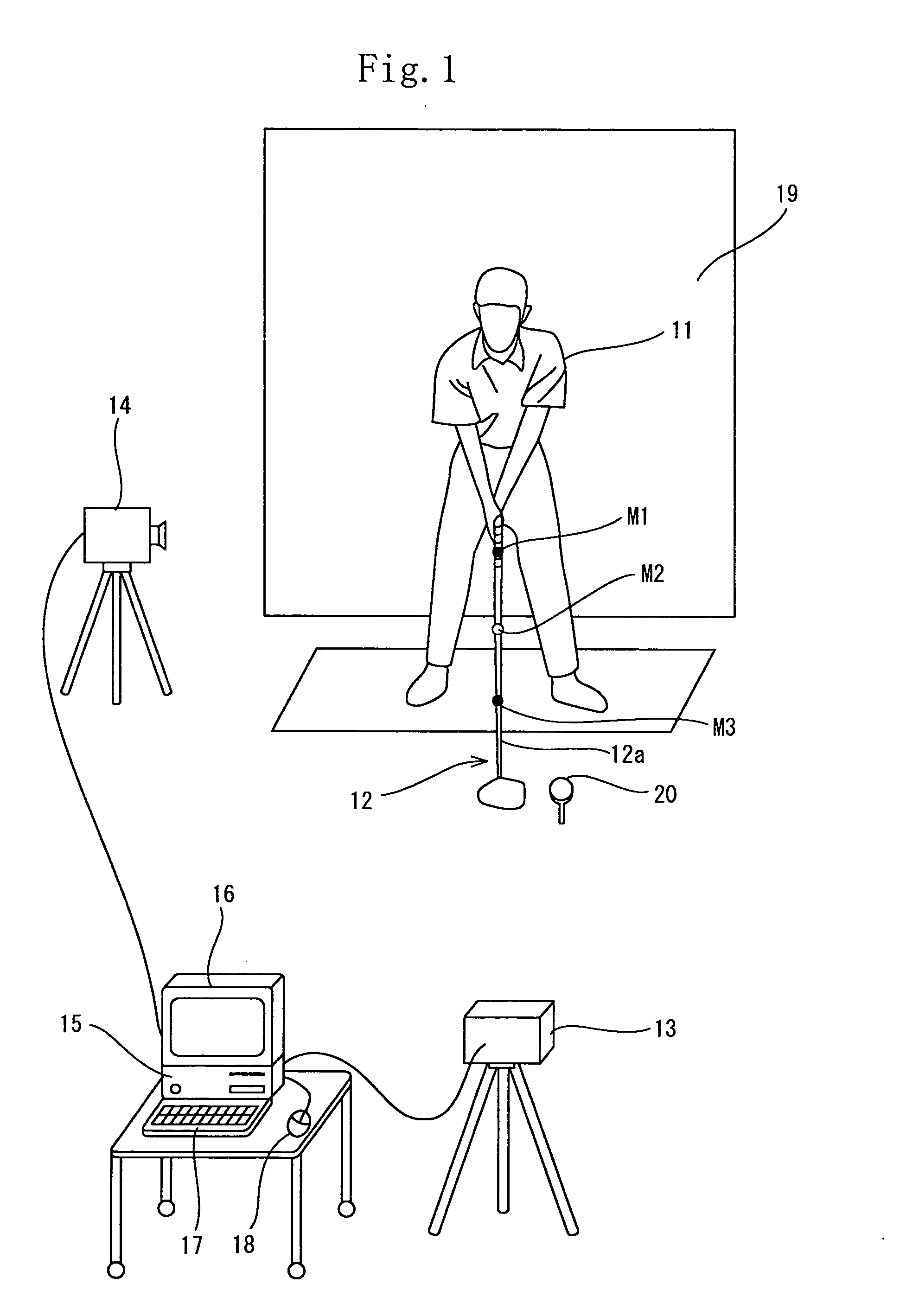
[0074]FIG. 1 shows a schematic view of the golf swing diagnosis system. The golf swing diagnosis system has a computer 15 serving as an information-processing apparatus; a monitor 16 serving as a display means connected to the computer 15; a key board 17 and a mouse 18, serving as input means, connected to the computer 15; and color CCD cameras 13 and 14, connected to the computer 15, installed at a position forward from a golfer 15 and at a position rearward from the golfer 15 in a ball fly line respectively. Three color marks M1, M2, M3 are mounted on required positions of a shaft 12a of a club 12 gripped by the golfer 11 to be diagnosed by spacing the color marks M1, M2, M3 at certain intervals.

[0075] The color marks M1 through M3 are mounted on the shaft 12a at equal intervals from a grip side to a head side. The colored mark M1 nearest to the grip is yellow. The colored mark M2 ...


PUM


Abstract

A computer (15) captures the colored moving image of the golfer (11) who swings by gripping a golf club (12) having colored marks (M1 through M3) attached to a shaft (12a) thereof. The computer (15) converts the colored moving image into a plurality of still images; executes binarization for each pixel of a plurality of the still images by using a specific threshold of color information and recognizes pixels, of the still images, which satisfy the threshold as positions of the colored marks (M1 through M3) and extracts a movement of the shaft (12a) by using a movement vector amount of one of the colored marks (M1 through M3 ) or by using a vector angle between two of the colored marks (M1 through M3). In this manner, the computer (15) automatically extracts check-point images.

Description

[0001] This nonprovisional application claims priority under 35 U.S.C. § 119(a) on Patent Application No(s). 2003-433539 filed in Japan on Dec. 26, 2003 and 2004-092419 filed in Japan on Mar. 26, 2004, the entire contents of which are hereby incorporated by reference. BACKGROUND OF THE INVENTION [0002] 1. Field of the Invention [0003] The present invention relates to a golf swing diagnosis system and more particularly to a system of automatically extracting check-point images effective for diagnosing a golfer's swing form with high accuracy. [0004] 2. Description of the Related Art [0005] There are proposed various kinds of apparatuses of photographing a golfer's swing, automatically computing information such as the flight distance, orbit, and the like of a hit ball by a computer, and displaying the obtained information for a golfer. These apparatuses allow the golfer to examine the flight distance, orbit, and the like of the hit ball. However, these apparatuses are incapable of pr...

Claims


Application Information

Patent Timeline
IPC IPC(8): A63B67/02A63B69/00A63B69/36H04N7/18
CPCA63B24/0003A63B2220/836A63B24/0021A63B69/3658A63B71/06A63B2024/0012A63B2024/0031A63B2071/0647A63B2220/05A63B2220/24A63B2220/30A63B2220/805A63B2220/807A63B2220/808A63B24/0006
Inventor SHIRAI, YOSHIAKISHIMADA, NOBUTAKAUEDA, MASAHIKOONUKI, MASAHIDE
Owner SHIRAI YOSHIAKI
Learn More