Fuel cell system and method of operating the same
a fuel cell and system technology, applied in the field of fuel cell systems, can solve the problems of accelerating the removal of water from the cathode, and achieve the effects of stable power, high reliability, and compact siz
- Summary
- Abstract
- Description
- Claims
- Application Information
AI Technical Summary
Benefits of technology
Problems solved by technology
Method used
Image
Examples
first embodiment
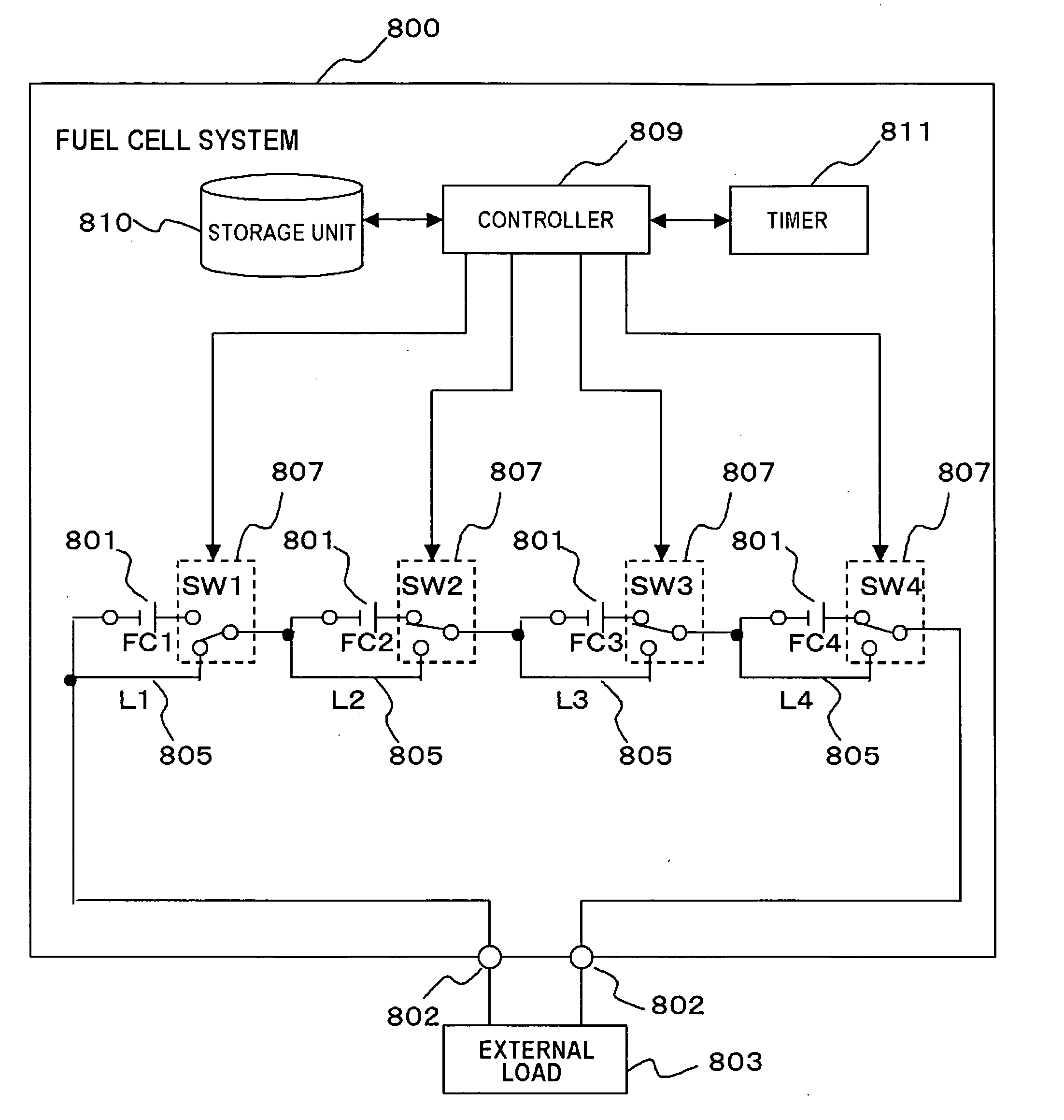
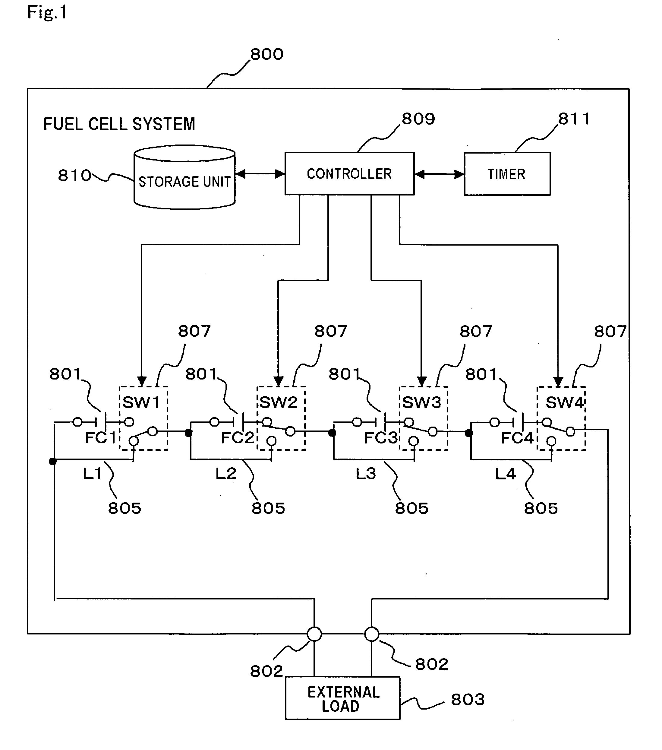
[0078]FIG. 1 is a block diagram schematically showing a configuration of a first embodiment of the fuel cell system according to the present invention.
[0079] As shown in FIG. 1, the fuel cell system 800 includes a plurality of fuel cell groups 801 mutually electrically connected in series. The fuel cell groups 801 are electrically connected in series to an external load 803 via terminals 802, to supply a power to the external load 803.
[0080] The fuel cell groups801 respectively include at least one unit cell of the fuel cell. The number of the unit cells included in the fuel cell group 801 does not have to be the same. In case where the fuel cell group 801 includes a plurality of unit cells, those unit cells are mutually electrically connected in series. Accordingly, a fewer number of unit cells can supply a necessary power to the external load 803, and the fuel cell system 800 can therefore be made smaller in size. The fuel cell groups 801, which are respectively designated as ‘F...
second embodiment
[0099]FIG. 3 is a block diagram schematically showing a configuration of a second embodiment of the fuel cell system according to the present invention. This embodiment is different from the first embodiment in that an auxiliary power source 821 is provided for each fuel cell group 801, for a substitutional use while the fuel cell group 801 is inactivated.
[0100] The fuel cell system 820 in the second embodiment includes four auxiliary power sources 821. The four auxiliary power sources 821, which are respectively designated by “AUX1”, “AUX2”, “AUX3” and “AUX4” in FIG. 3, will be hereinafter designated as “AUXi” to designate an i-th auxiliary power source (i=1 to N, where N is the number of fuel cell groups, which may be four as shown in FIG. 3).
[0101] The auxiliary power source 821 may be constituted of for example a lithium ion secondary cell or an electric double layer capacitor. Here, while four auxiliary power sources 821 are provided in this embodiment, the present invention ...
third embodiment
[0111]FIG. 5 is a fragmentary block diagram schematically showing a configuration of a third embodiment of the fuel cell system according to the present invention. The fuel cell system 830 in this embodiment is different from that of the first embodiment in further including a voltmeter 831 which measures a voltage of the fuel cell groups 801. Also, in this embodiment, the auxiliary power source 821 may be provided on the auxiliary line Li, as described in the second embodiment.
[0112]FIG. 5 shows only one out of the plurality of fuel cell groups 801, which is designated as “FCi” (i=1 to N, where N=4 in this embodiment). The voltmeter 831, designated as “VMi” in FIG. 5, is disposed at both ends of the i-th fuel cell group FCi.
[0113] The controller 809 monitors a voltage value of each fuel cell group FCi measured by the voltmeter VMi disposed on each fuel cell group FCi, and controls an operation of the fuel cell system 830 such that the fuel cell group FCi is electrically disconnec...
PUM
| Property | Measurement | Unit |
|---|---|---|
| voltage measuring | aaaaa | aaaaa |
| output voltage | aaaaa | aaaaa |
| current | aaaaa | aaaaa |
Abstract
Description
Claims
Application Information
 - R&D Engineer
- R&D Manager
- IP Professional
- Industry Leading Data Capabilities
- Powerful AI technology
- Patent DNA Extraction
Browse by: Latest US Patents, China's latest patents, Technical Efficacy Thesaurus, Application Domain, Technology Topic, Popular Technical Reports.
© 2024 PatSnap. All rights reserved.Legal|Privacy policy|Modern Slavery Act Transparency Statement|Sitemap|About US| Contact US: help@patsnap.com


