Method and device for alignment of a substrate

a substrate and alignment technology, applied in the field of lithographic apparatus and methods, can solve the problems of inconvenient use of known gripper arms, reduced price, and reduced vacuum system components, so as to reduce the time for determining position, reduce the number of readings per sensor, and improve the effect of accuracy

Active Publication Date: 2005-06-30
ASML NETHERLANDS BV
View PDF4 Cites 15 Cited by
  • Summary
  • Abstract
  • Description
  • Claims
  • Application Information

AI Technical Summary

Benefits of technology

[0025] A position of the substrate may be determined when the substrate is in the chamber, prior to being gripped by the gripper, or after being gripped by the gripper and while being transferred to the support. The gripper position is controlled, on the basis of the sensor signal, to correct an offset of the substrate centre relative to the support, at the position of gripping of the substrate or at the position of providing of the substrate to the support. In this manner an accurate positioning of the substrate on the support can be achieved with an accuracy of several micrometers or less.
[0027] In a vacuum environment, such as for instance in EUV-lithography apparatus, the method according to an embodiment of the present invention reduces the number of take-overs of the substrate when it is transferred to a support. The manipulator movements to transfer the substrate from the load lock into the vacuum chamber are used to correctly position the substrate, either by an offset in the gripping position, or by an offset in position when providing the substrate to a support (pre-alignment support). A separate centering chuck in the chamber, such as commonly used in conventional lithographic projection apparatus, can be omitted in this way, and transfer from such a centering chuck to the (pre-alignment) support is avoided. This results in a reduced number of transfers, reduced transfer times and reduced substrate contamination.
[0032] As space in a load lock is limited, the sensor is advantageously placed outside of the load lock. Measuring the position of the substrate “in the flight” furthermore results in a reduced time for determining the position of the substrate.
[0034] In a further embodiment of the invention, the sensor is placed in proximity to the (pre-alignment) support. In this case substrates can be placed onto the (pre-alignment support by a further gripper which does not interface with a load lock. Also, the centering correction can be carried out simultaneously with the movement of the substrate towards the (pre-alignment) support (z-direction). This results in a faster centering using less steps, resulting in reduced contamination (dirt, temperature, etc.).

Problems solved by technology

With conventional apparatus, however, positioning via the gripper arm may lead to mechanical inaccuracies in offset in the range of 100 micrometers or more.
For lithographic purposes, in which the pattern on the substrate should be accurately aligned on the substrate stage with accuracies of several micrometers or less, the known gripper arms may not be suitable.
Furthermore, the reduction of the number of mechanical components results in reduced prices and a reduced number of components of the vacuum system.

Method used


Image

  • Method and device for alignment of a substrate
  • Method and device for alignment of a substrate
  • Method and device for alignment of a substrate

Examples


second embodiment

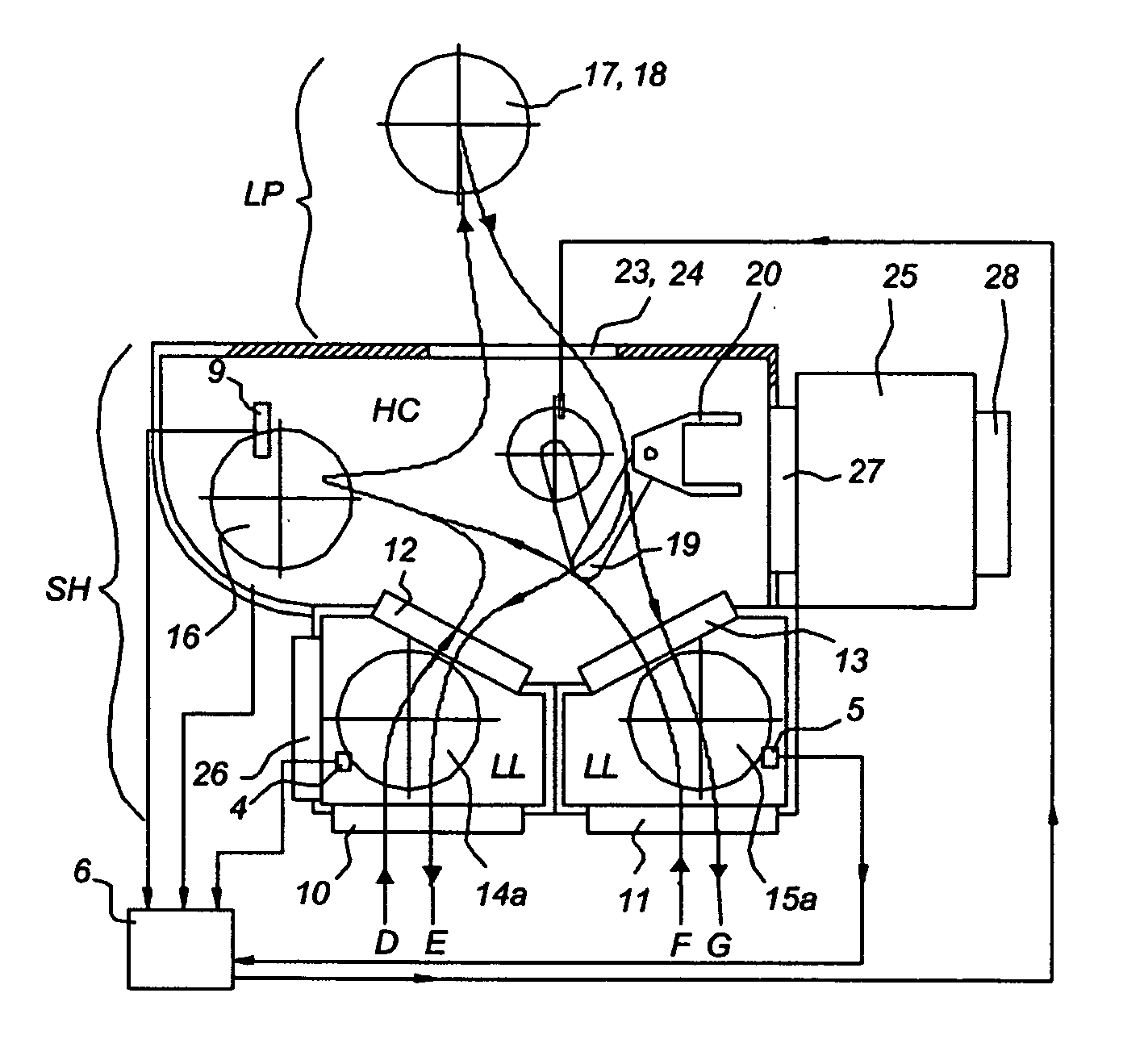
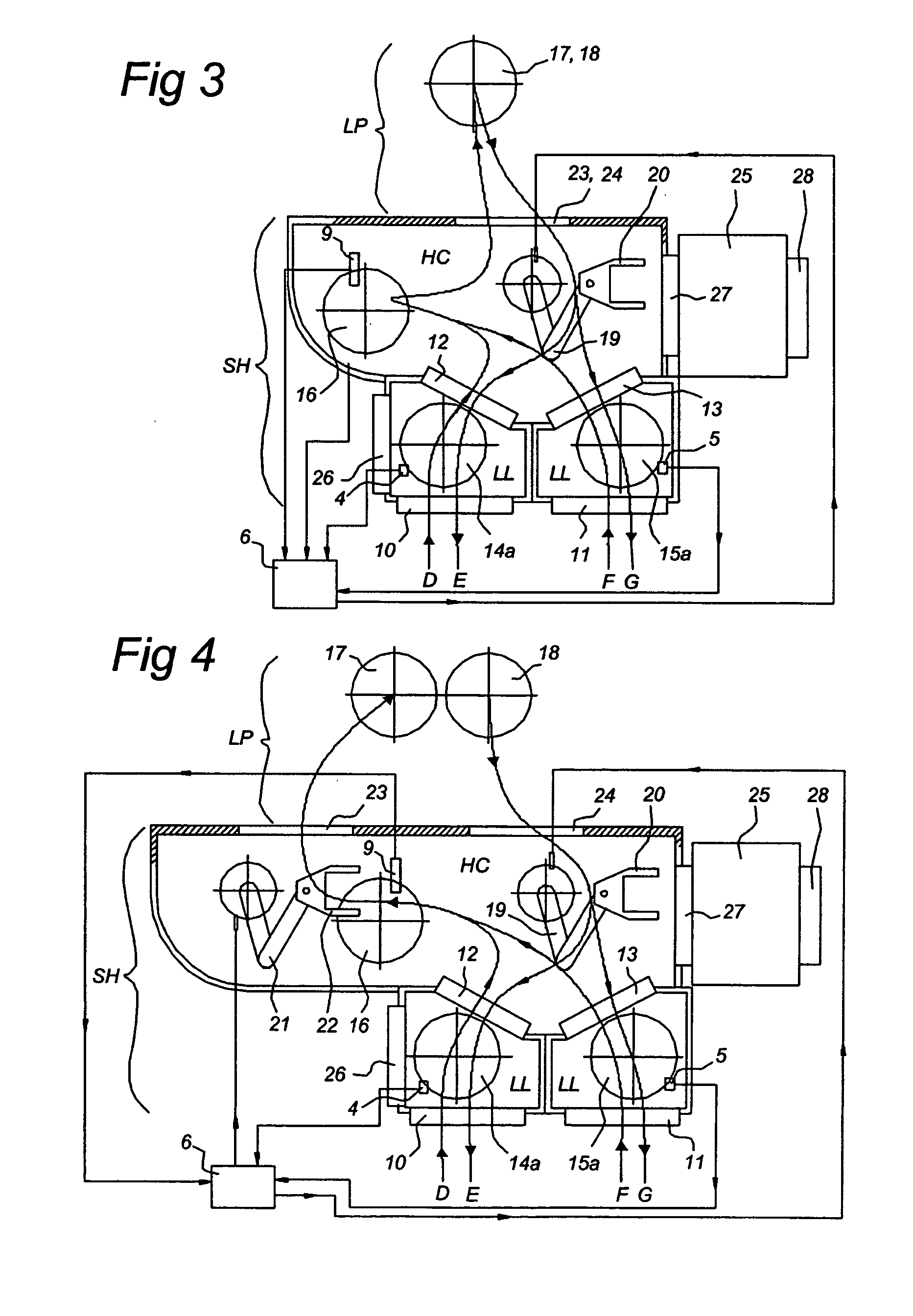
[0057] FIGS. 3 and FIG. 4 depict a lithographic projection assembly according to a first and a second embodiment, respectively, of the invention. In both Figures, the following modules will be recognized: two load locks LL; the handler chamber HC, in combination with two load locks LL designated as a substrate handler SH; and the lithographic projection apparatus LP, including a projection chamber.

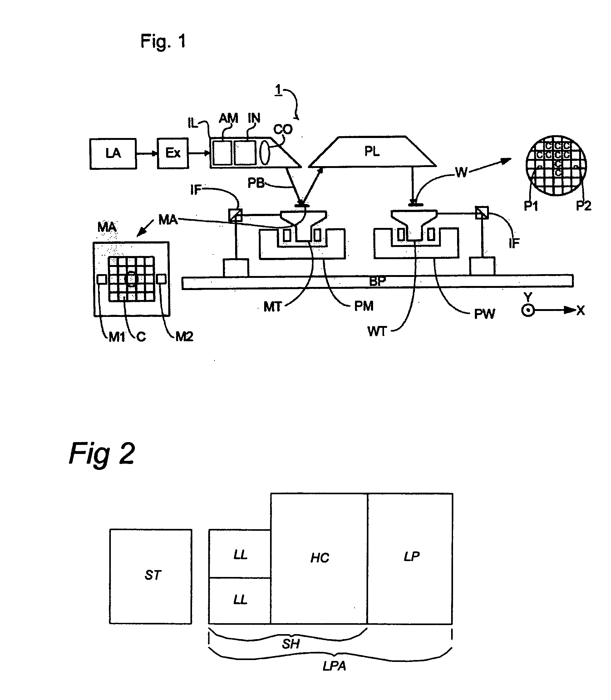
[0058] In the latter module LP, the arrangement is not shown in detail but can be understood by example from FIG. 1.

[0059] Adjacent to the load locks LL opposite to the handler chamber HC another module may be present such as a substrate track ST (see FIG. 2), that is configured to supply and remove substrates to and from the load locks LL.

[0060] In each load lock LL, a door 10, 11 is present, which door is configured to allow transfer of substrates between the first environment and the load lock LL. At the opposite side thereof, each load lock is provided with a door 12, 13 that are con...

first embodiment

[0067] Upon transferring substrates between the handler chamber HC and the lithographic projection apparatus LP and vice versa, a substrate passes an entrance 23 or 24. Comparable with the difference in the previous paragraph, in FIG. 3 the entrance between the handler chamber and load and unload position 23, 24 coincide.

[0068] Another difference between the first and second embodiment of FIG. 3 and FIG. 4 relates to the transport devices. The first embodiment of FIG. 3 includes one manipulator 19 having a gripper 20, while the second embodiment depicted in FIG. 4 includes next to the first manipulator a second manipulator, also having a gripper 22. Both manipulators are in these embodiments a robot, a SCARA robot, but also other robots or other manipulators are conceivable.

[0069] The robots are adapted for the following operations: [0070] 1. picking a substrate from one of the load locks LL and transferring the substrate to the pre-processing position 16; and / or [0071] 2. picking ...


PUM


Abstract

Embodiments of the invention include a method of placing a substrate on a support. In an embodiment of the invention, the method includes determining a position of the substrate relative to a reference position via a sensor which outputs a sensor signal to a control unit, the determining including detecting the position of the substrate in a chamber, and determining a gripping position on the substrate; gripping the substrate at the gripping position with a gripper controlled by the control unit, and providing the substrate in a defined position on the support member, the providing including moving the substrate to a fixed position relative to the support member such that the center of the substrate arrives at a predetermined position on the support member.

Description

PRIORITY INFORMATION [0001] This application claims priority from European Patent Application No. 03078206.04, filed Oct. 10, 2003, the content of which is herein incorporated by reference in its entirety. BACKGROUND [0002] 1. Field of the Invention [0003] The invention relates to lithographic apparatus and methods. [0004] 2. Description of Related Art [0005] A lithographic apparatus typically includes a radiation system configured to condition a beam of radiation, a support structure configured to support a patterning device, the patterning device serving to pattern the beam of radiation according to a desired pattern, a substrate table configured to hold a substrate, and a projection system configured to project the patterned beam onto a target portion of the substrate. [0006] The term “patterning device” as here employed should be broadly interpreted as referring to a device that can be used to endow an incoming radiation beam with a patterned cross-section, corresponding to a pa...

Claims


Application Information

Patent Timeline
IPC IPC(8): G03F7/20G03B27/58G03F9/00H01L21/027H01L21/677H01L21/68
CPCG03F7/7075G03F9/7096G03F9/7011
Inventor ANDREAS HAZENBERG, JOHANNES MARTINUSJACOBUS TINNEMANS, PATRICIUS ALOYSIUSVISSER, RAIMOND
Owner ASML NETHERLANDS BV
Why Eureka
Try Eureka