
Load sensor with use of crystal resonator

a technology of crystal resonators and load sensors, which is applied in the direction of instruments, apparatus for force/torque/work measurement, device material selection, etc., can solve the problems of reducing the q (quality factor) of the oscillator, and the inability to perform measurements with so as to achieve a high degree of accuracy and minimize the oscillation. , the effect of not reducing the q

Inactive Publication Date: 2005-06-30
YAMATO SCALE CO LTD +1
View PDF12 Cites 11 Cited by
  • Summary
  • Abstract
  • Description
  • Claims
  • Application Information

AI Technical Summary

Benefits of technology

The present invention provides a load sensor using a crystal resonator with high Q and accuracy. The crystal resonator is supported by supporting bodies that minimize the transmission of oscillation to the supporting bodies, reducing the impact on the surrounding mechanism and improving accuracy. The central portion of the crystal resonator can have symmetrical grooves to further reduce energy loss and increase Q as an oscillator. The end faces of the crystal resonator are designed to minimize the areas in contact with the supporting bodies, restraining resonating and improving accuracy. The fabrication of the crystal resonator is simpler than other load sensors.

Problems solved by technology

Due to this, there exists such a problem that its Q (Quality factor) as an oscillator decreases.
Furthermore, since the thickness shear oscillation of the quartz resonator 300 is transmitted to the supporting bodies 302, 302, thereby causing the surrounding mechanism to resonate, there exists such a problem that measurements can not be performed with a high degree of accuracy.

Method used


Image

  • Load sensor with use of crystal resonator
  • Load sensor with use of crystal resonator
  • Load sensor with use of crystal resonator

Examples


embodiment 1

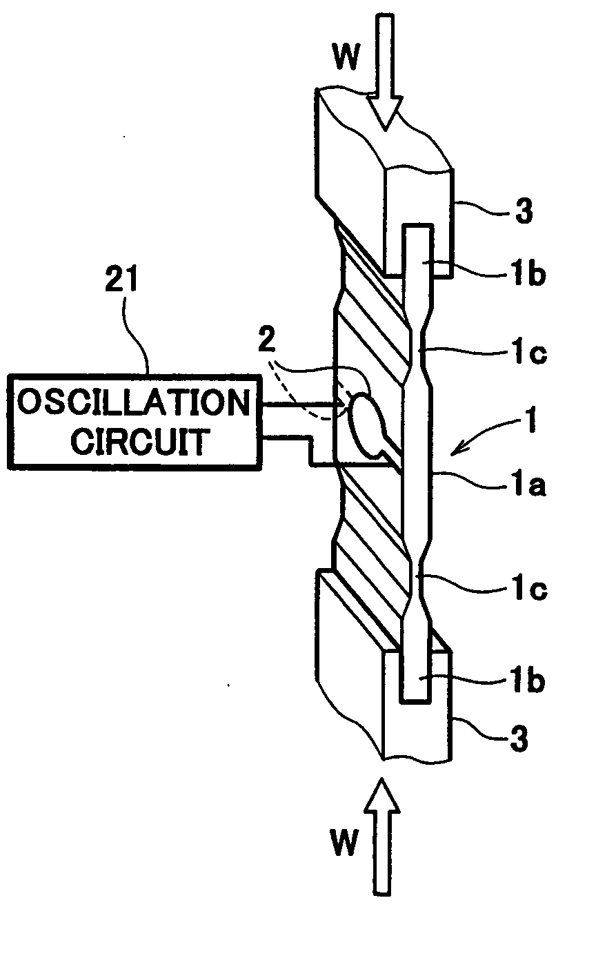
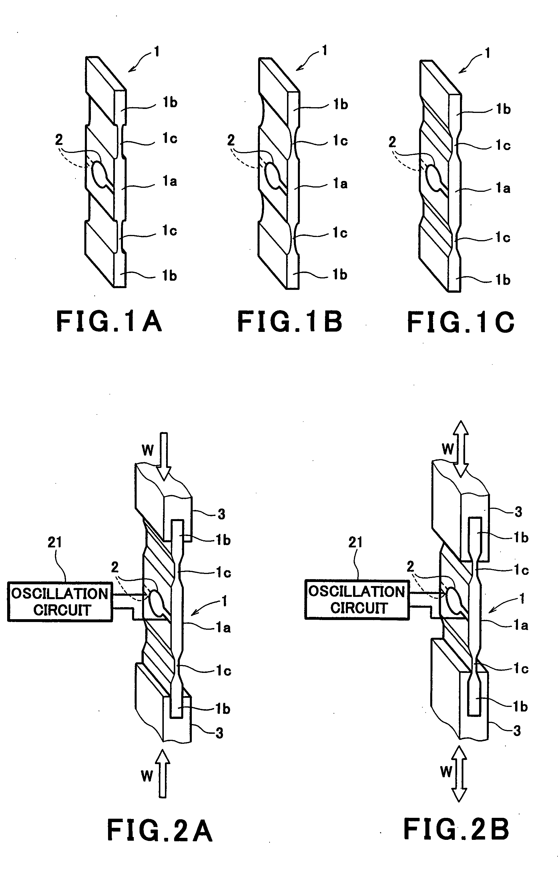
[0028]FIGS. 1A-1C are perspective views showing a crystal resonator used in a load sensor according to Embodiment 1 of the present invention. In FIGS. 1A-1C, a long-plate shape crystal resonator 1 is an AT-cut quartz piece capable of oscillating in a thickness shear oscillation mode in a length direction of the quartz resonator 1.

[0029] Excitation electrodes 2, 2 serving as exciting means are respectively affixed to both surfaces of a central portion la of the quartz resonator 1. The central portion 1a starts the thickness shear oscillation in the length direction of the crystal resonator 1 when an electric signal is supplied to the central portion la of the crystal resonator 1 through the excitation electrodes 2, 2. It should be noted that these electrodes 2, 2 are connected to an oscillation circuit described below.

[0030] As shown in FIG. 1A, channel-shaped grooves in cross-section are respectively provided in the plate width direction on both surfaces of middle portions 1c, 1c,...

embodiment 2

[0052]FIGS. 7A and 7B are perspective views showing a constitution of a load sensor with a crystal resonator according to Embodiment 2 of the present invention. In FIG. 7A, a crystal resonator 4 is a rectangular AT-cut quartz piece and retained between rectangular parallelepiped supporting bodies 6, 6 which are respectively in contact with and pressing end faces of one end portion and the other opposing end portion thereof from the outside. The end faces are filed so as to be circular-arc-shaped in cross-section. Since the other elements are identical to those of Embodiment 1, the same or corresponding parts are denoted by the same reference numerals and as such will be not described herein.

[0053] Since the end faces of the crystal resonator 4 are circular-arc-shaped, the contacting areas with the supporting bodies 6, 6 are smaller as compared with the case where the end faces are flat. Because of this, when the crystal resonator 4 oscillates in the thickness shear oscillation mode...


PUM

PropertyMeasurementUnit
thicknessaaaaaaaaaa
oscillation frequencyaaaaaaaaaa
oscillation energyaaaaaaaaaa

Abstract

Excitation electrodes are respectively affixed to central portions of both surfaces of a long plate-shaped AT-cut crystal resonator, the central portion starts a thickness shear oscillation in the length direction of the crystal resonator when an electric signal is applied to the central portion of the crystal resonator through the excitation electrodes. And, channel-shaped, half-circular-shaped, or trapezoid grooves in cross-section are respectively formed in the plate width direction on middle portions between the center portion and end portions of the crystal resonator. These grooves are formed so as to be symmetrical with respect to a thicknesswise central position of the crystal resonator through a well-known etching technique such as photo-etching and the like.

Description

CROSS-REFERENCE TO RELATED APPLICATIONS [0001] This application is a division of U.S. patent application Ser. No. 10 / 163,858 entitled LOAD SENSOR WITH USE OF CRYSTAL RESONATOR, filed Jun. 5, 2002, now pending, which in turn claims priority to Japanese Patent Application No. 2001-175327, filed on Jun. 11, 2001. The entire disclosure of each of these applications is herein incorporated by reference for all purposes.FIELD OF THE INVENTION [0002] The present invention relates to a load sensor using a crystal resonator for measuring a load, and more specifically to a load sensor capable of minimizing as much as possible outward leakage of oscillation energy of a thickness shear oscillation caused by a crystal resonator. BACKGROUND OF THE INVENTION [0003] Strain-gauge load cells have been widely used as a load sensor for electronic weighing scales. However, in these years, with rapid advance in electronic measurement technologies, load sensors which are more accurate than the strain-gauge...

Claims


Application Information

Patent Timeline
Patent Type & Authority Applications(United States)
IPC IPC(8): G01G3/13G01G3/16G01L1/10H01L41/08H01L41/18
CPCG01G3/13
Inventor YAMANAKA, MASAMIADACHI, MOTOYUKICHIBA, AKIOONO, KOZO
Owner YAMATO SCALE CO LTD
Learn More