
Stent mounted valve

a valve and stent technology, applied in the field of medical devices, can solve the problems of child simply “outgrowing” a valve, set of even greater challenges, etc., and achieve the effects of promoting or inhibiting the infiltration of cells onto the valve material, and preventing the formation of thrombosis

Active Publication Date: 2005-06-23
JUSTINO HENRI
View PDF23 Cites 754 Cited by
  • Summary
  • Abstract
  • Description
  • Claims
  • Application Information

AI Technical Summary

Benefits of technology

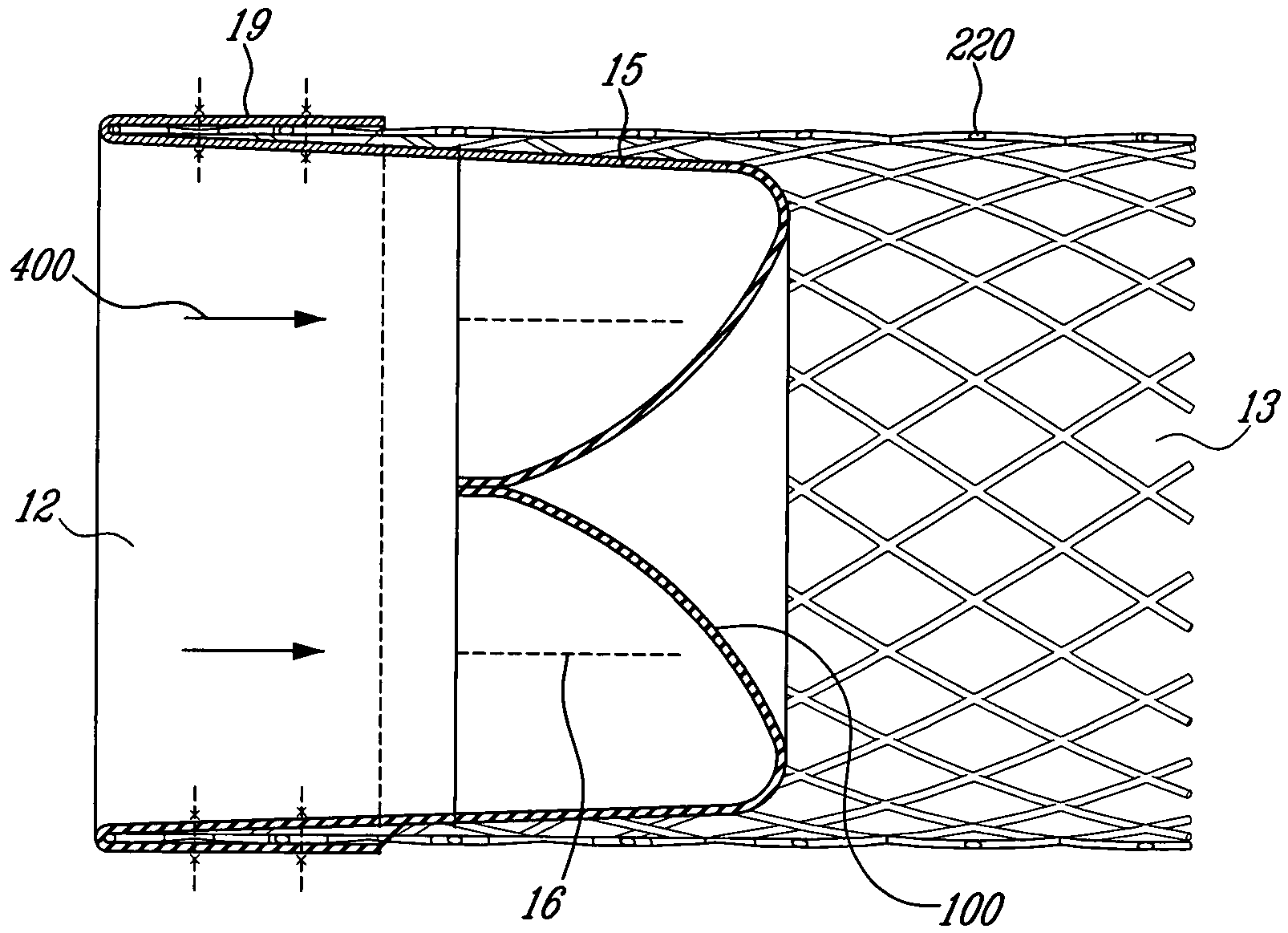
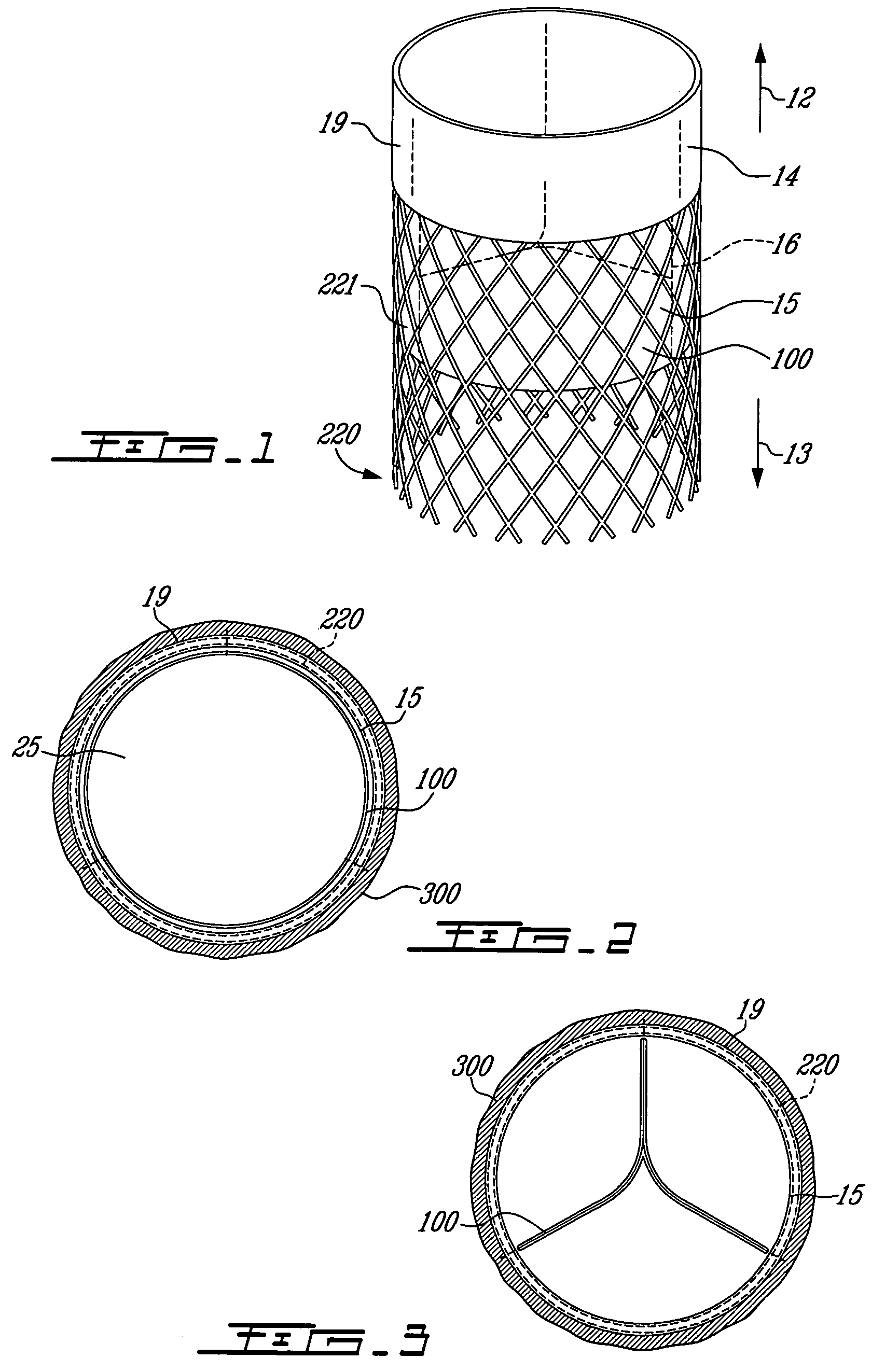
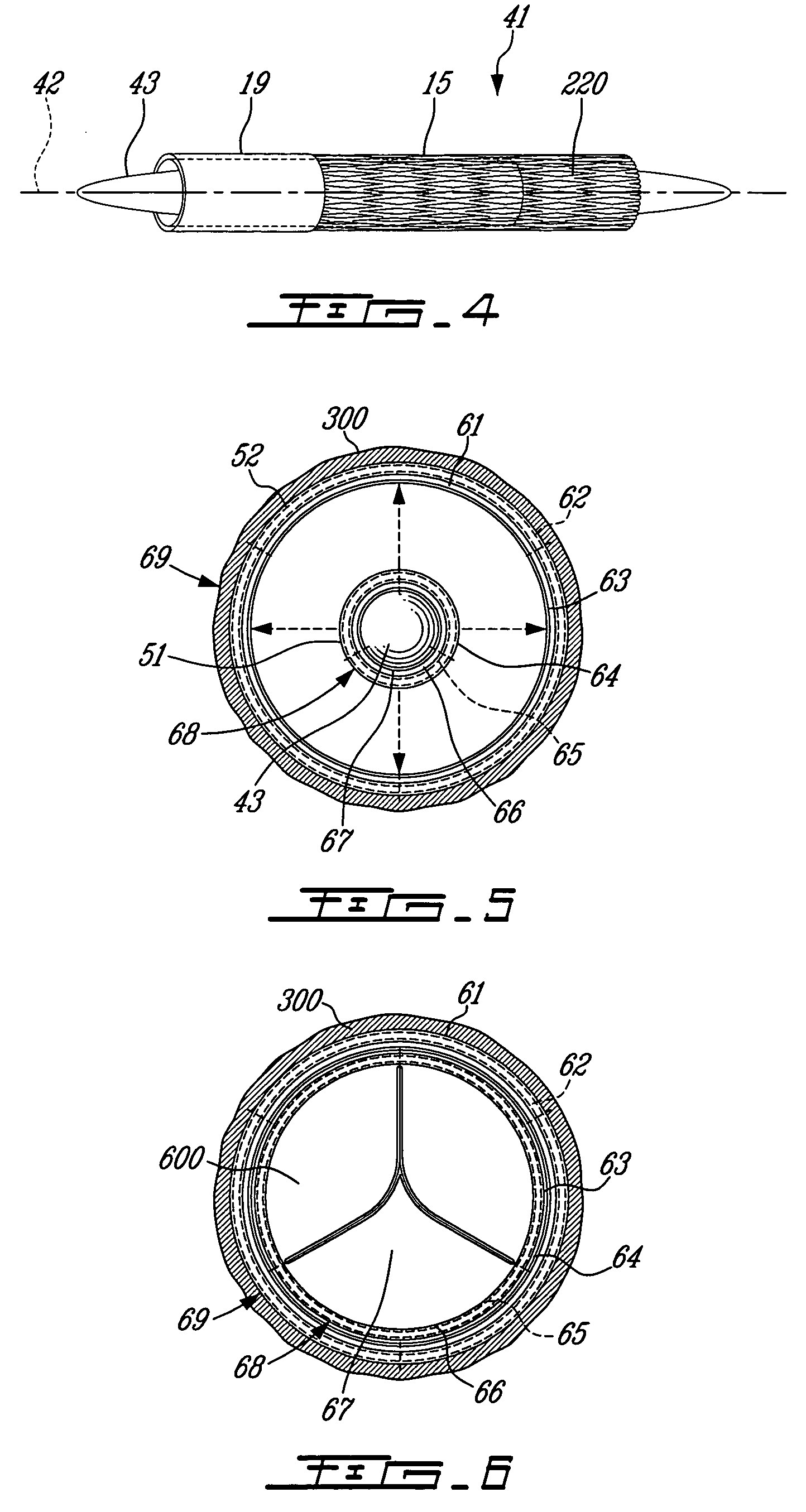
"The present invention provides a synthetic valve that can be implanted in children and adults with a smaller delivery system. The valve is designed to be replaced percutaneously, and can be collapsed into a sheath size of 12-14 F or smaller for implantation. The valve can be expanded with a balloon and does not require anticoagulants or damage to blood cells and platelets. The valve is also designed to prevent blood clotting and infiltration of the body's own cells. The valve is made of a single tubular membrane, which simplifies the manufacturing process and improves strength. The invention also provides a method to replace a worn or defective valve, and a mechanism to prevent migration of the device in patients with high pressures distal to the prosthetic valve."

Problems solved by technology

Creation of a valve that is implantable in children is met with a set of even greater challenges than a valve designed for adults.
First, the valve must be implanted through a much smaller delivery system.
Second, although valve failure due to deterioration of the leaflet material is a universal concern for patients of all ages, the rapid body growth found in children means that a child may simply “outgrow” a valve even without deterioration in leaflet function (by virtue of an orifice which may become too small for a child after a period of rapid growth, despite proper leaflet mobility).

Method used


Image

  • Stent mounted valve
  • Stent mounted valve
  • Stent mounted valve

Examples


Embodiment Construction

[0074] In accordance with an aspect of the invention, preferred embodiments of a prosthetic valve are provided. It should be understood that throughout this application, the term “prosthetic valve” is used to mean any valve, whether implanted surgically or percutaneously, which is not a completely naturally occurring valve. This includes mechanical valves, biological valves made from living tissues, and polymer valves which combine features from both mechanical valves and biological valves.

[0075] The replacement of the pulmonary valve in a small child will be discussed in detail as an example. However, it should be understood that the present invention is not limited to this valve, and may be used to replace any of the cardiac valves, any venous valves, or any other valves in the body. As well, this invention can be used to establish valves in the body where no natural valves exist. For example, valves can be placed in the branch pulmonary arteries in patients where the main pulmon...


PUM


Abstract

There is described a prosthetic valve to be inserted into a body lumen, the valve having leaflets that are spread apart during forward flow of fluid to create an orifice, and the leaflets coming into contact with each other during reverse flow of fluid, thereby impeding the reverse flow of fluid, the valve comprising: a hollow, cylindrical stent having an inner surface and an outer surface, and having a first and a second open end; and valve means formed from a single tubular membrane, the membrane mounted to the stent, the membrane having a graft portion internally folded and bonded to itself at a plurality of points to form pouches such that the leaflets extend from the pouches, and a sleeve portion on an outer surface of the stent to secure the membrane thereto.

Description

FIELD OF THE INVENTION [0001] The invention relates to the field of medical devices and, more specifically, to the field of prosthetic valves inserted percutaneously or surgically. BACKGROUND OF THE INVENTION [0002] The primary function of a valve is to ensure that a fluid flows only in one direction. There are many valves in the human body, helping to make sure that homeostasis is maintained in an efficient manner. There are four valves in the heart that regulate the direction and flow of blood. The pulmonary valve directs blood from the right ventricle into the main pulmonary artery where it flows into the lungs. The aortic valve directs blood towards the aorta, the main artery of the body. The mitral and tricuspid valves are internal to the heart, directing blood flow between the atria and ventricles. Valves may fail to function due to inadequate opening (also known as narrowing, or stenosis), inadequate closure (also known as leaking, or regurgitation or insufficiency), or a com...

Claims


Application Information

Patent Timeline
Patent Type & Authority Applications(United States)
IPC IPC(8): A61F2/06A61F2/24
CPCA61F2/2412A61F2/2418A61F2250/0082A61F2230/0054A61F2220/0016A61F2220/005A61F2220/0008
Inventor JUSTINO, HENRI
Owner JUSTINO HENRI
Learn More