
Apparatus for modulation in base station with smart antenna

a technology of smart antenna and antenna, applied in the direction of electrical apparatus, diversity/multi-antenna system, spatial transmit diversity, etc., can solve the problems of increasing cost due to the increase of many antennas, and reducing the frequency efficiency. , to achieve the effect of reducing the reliance on hardware components

Inactive Publication Date: 2005-06-23
ELECTRONICS & TELECOMM RES INST
View PDF9 Cites 11 Cited by
  • Summary
  • Abstract
  • Description
  • Claims
  • Application Information

AI Technical Summary

Benefits of technology

[0008] The present invention is directed to an apparatus for modulation in a base station with a smart antenna, which can solve problems such as bulky hardware components for modulation and low compatibility due to a change in the number of base station sectors and the number of antennas, that is, a time division multiplexing method is fully used to decrease reliance on the hardware components, and a sector beam selector and a TX beam former are used to be compatible with a conventional base station system without separate hardware components, for example, one hardware component allows a smart antenna base station system of 3 sectors and 8 antennas to be readily compatible with a conventional base station system of 3 sectors and 2 antennas or 6 sectors and 2 antennas.

Problems solved by technology

In particular, the smart antenna system is called an antenna array system to be applied to mobile communication, and its frequency efficiency has been recently exhausted.
However, the smart antenna system has disadvantages that cost is increased due to an increase of many antennas; base station transceivers have a complicated structure due to the use of multiple antennas in the base station; it is too complicated to manage resource and channel allocation; there is required compatibility with a conventional system; etc.

Method used


Image

  • Apparatus for modulation in base station with smart antenna
  • Apparatus for modulation in base station with smart antenna
  • Apparatus for modulation in base station with smart antenna

Examples


Embodiment Construction

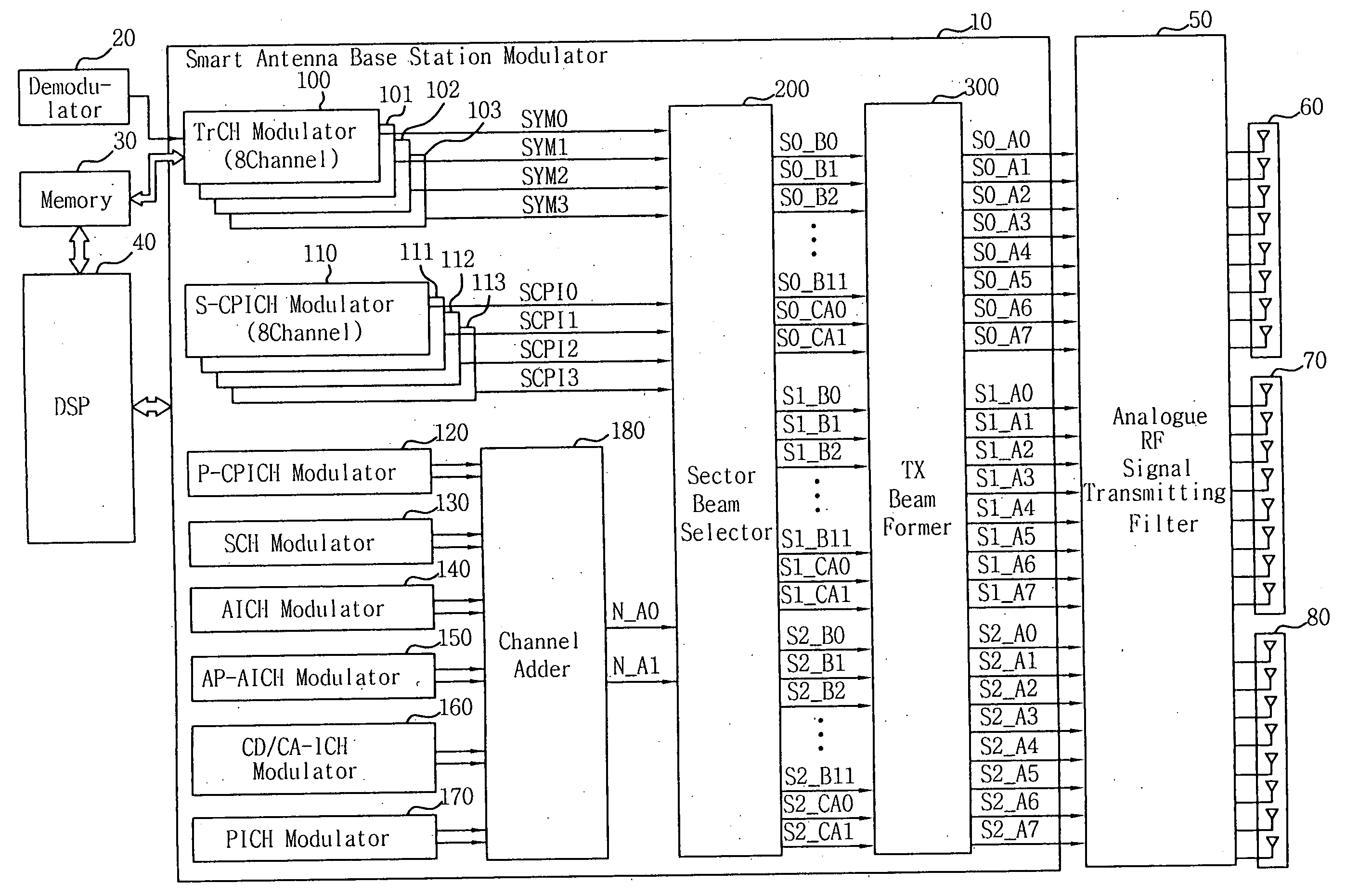
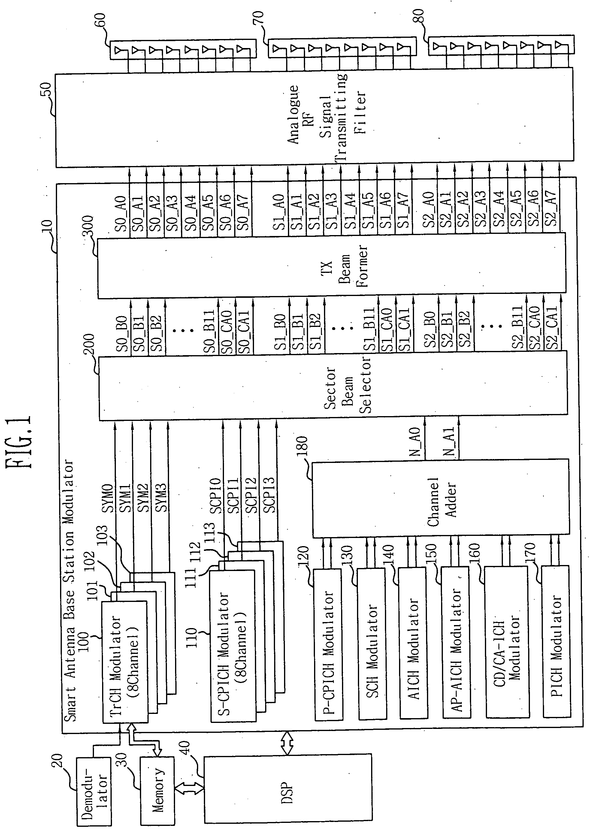
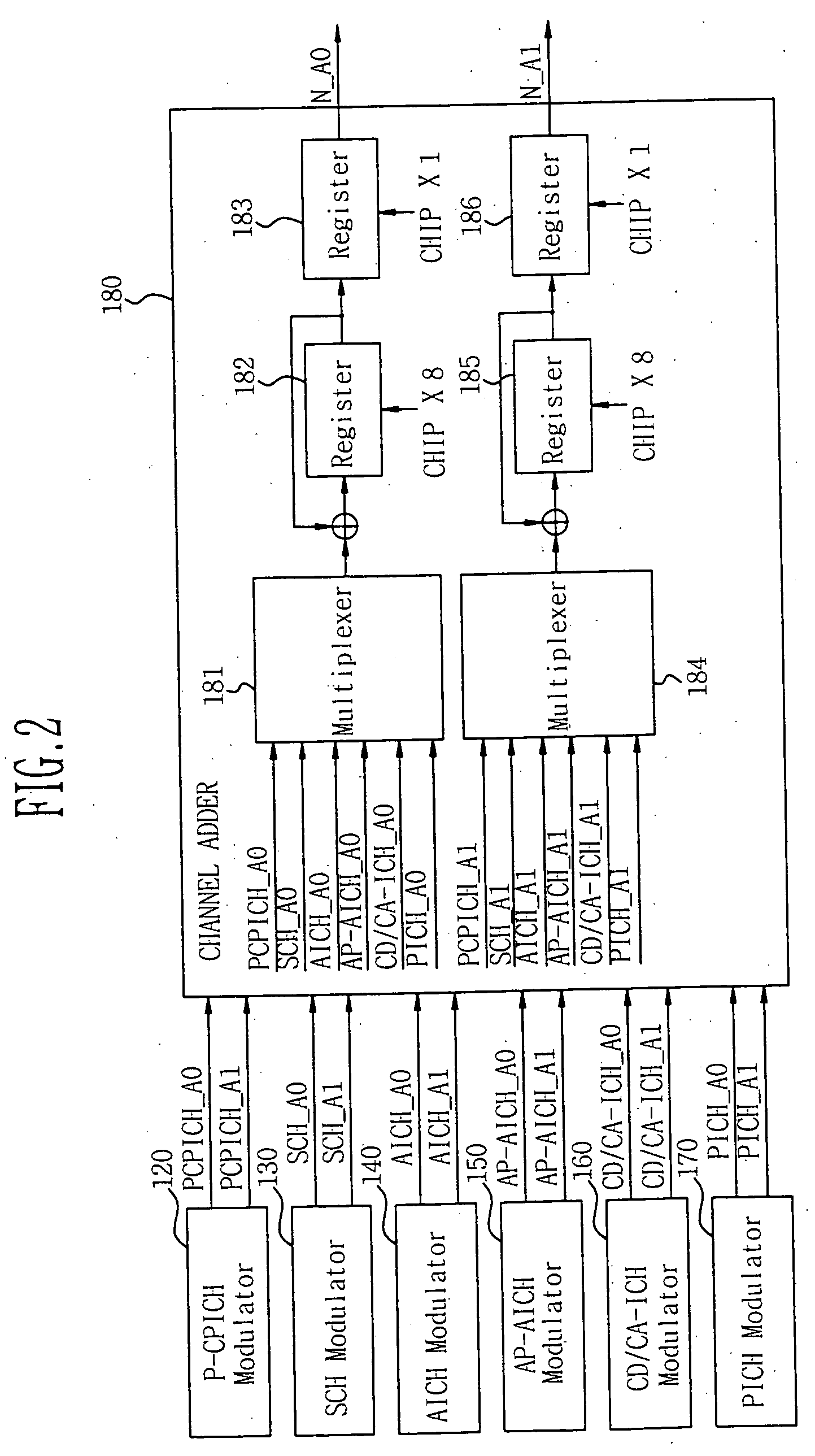
[0015] The present invention will now be described more fully hereinafter with reference to the accompanying drawings, in which preferred embodiments of the invention are shown. This invention may, however, be embodied in different forms and should not be construed as limited to the embodiments set forth herein. Rather, these embodiments are provided so that this disclosure will be thorough and complete, and will fully convey the scope of the invention to those skilled in the art.

[0016] According to the present invention, an apparatus for modulation in a base station with a smart antenna has developed to meet a WCDMA specification employed in 3rd generation partnership project (3GPP), but may be applied to a CDMA2000 employed in 3GPP2 or a specification employed in 4th generation partnership project (4GPP) or the like which is being currently developed.

[0017] In the present invention, a smart antenna system will be described by way of example, which requires parameters as follows:...


PUM


Abstract

Provided is an apparatus for modulation in a base station with a smart antenna. The smart antenna system has many advantages that it is possible to deal with the large volume of subscribers; communication quality is increased; etc. However, the smart antenna system has disadvantages that cost is increased due to many antennas; base station transceivers have a complicated structure due to multiple antennas per base station; it is too complicated to manage resource and channel allocation; there is required compatibility with a conventional system; etc. The present invention provides an apparatus for modulation in a base station with a smart antenna, which can solve the foregoing problems by employing a modulator using a time division multiplexing method, a sector beam selector, and a TX beam former, thereby providing good compatibility regardless of a change in the number of base station sectors and the number of antennas.

Description

BACKGROUND [0001] 1. Field of the Invention [0002] The present invention relates to an apparatus for modulation in a base station with a smart antenna. [0003] 2. Description of the Related Art [0004] A smart antenna system uses multiple antenna elements and adjusts a gain and a phase of signals received from the respective antenna elements, so that a base station receives a signal transmitted from a user in only a desired direction and largely decreases a noise signal level due to multiple-access interference with signals transmitted from other directions, thereby improving performance of the system and increasing channel capacity of the base station. In particular, the smart antenna system is called an antenna array system to be applied to mobile communication, and its frequency efficiency has been recently exhausted. Further, according as the mobile communication has recently been improved in quality and the system adaptive to high-speed data transmission has actively researched, ...

Claims


Application Information

Patent Timeline
IPC IPC(8): H04B7/04H04B7/155H04B7/06H04B7/216H04W16/28H04W88/08
CPCH04B7/0491H04W88/08H04W16/28H04B7/0617H04B7/04
Inventor LIM, IN GIKIM, IL GYUPARK, HYUNG ILBANG, SEUNG CHANJUNG, HEE BUM
Owner ELECTRONICS & TELECOMM RES INST
Learn More